It’s been awhile since my last post, just too many things to do and age is slowing me down. This post is about work I did from mid-August to mid-September but never got around to posting. I’m currently finishing up some added insulation to my barn so I can get back to car work by February. This post covers undercoating removal, door hinge removal and fabrication of new rocker panels, in that order.
Undercoating Removal
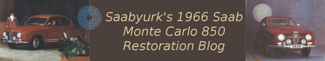
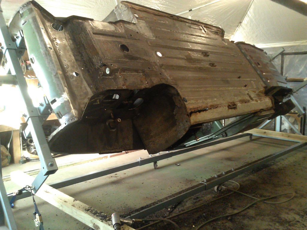
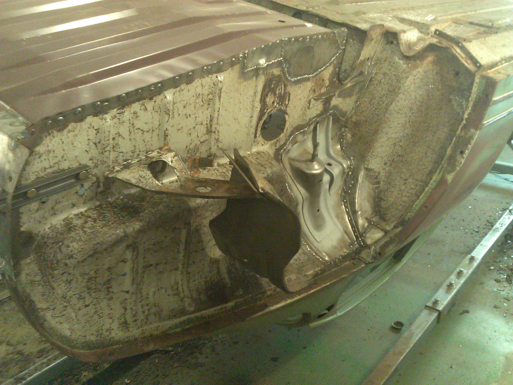
With the car on the rotisserie, it was now time to put my air hammer and modified chisel to work on the undercoating. As previously described, the chisel has slightly rounded ends to prevent digging in, especially on contours, and it is not especially sharp. I use only about 40-45 psi and try to do this in cooler weather. Warm undercoating doesn’t break away easily because it gets soft. Winter would have been a better time to do this but I got good results on cool days. Not much description needed. Figures 1-5 below show the results.
Figure 6 shows a Dremel oscillating tool with a scraper blade being used to remove remnants of the heavy felt that I had pulled off. Some of the adhesive residue remains but it should help later to have all the paper off.
1. Undercoating Removed – Floor
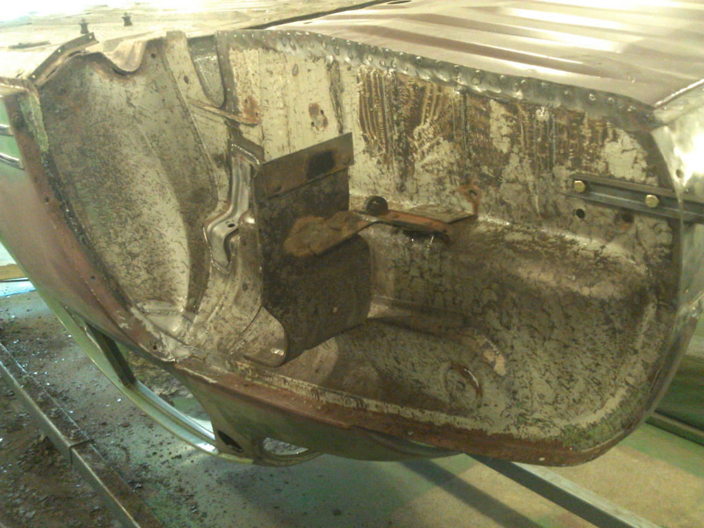
2. Passenger, Rear Wheel Housing
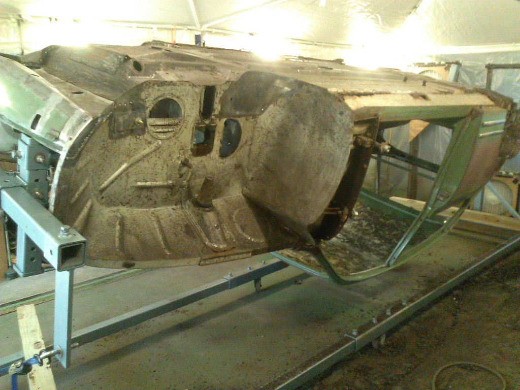
3. Passenger, Front Wheel Housing
4. Driver, Rear Wheel Housing

5. Driver, Front Wheel Housing

6. Removing Felt Remnants
Door Hinge Removal
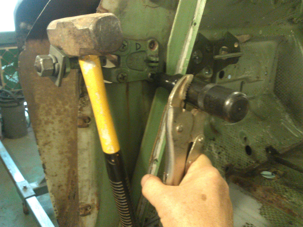
Figures 7-9 below show some steps in removing the door hinges. I only cover this here because it’s always difficult to remove the rusted Phillips head screws. Heat in the right area always helps but I try to remove them without the use of heat. An impact tool as shown in Figure 7 is essential. I was unable to break most of them free until I gripped the impact tool with vice-grip pliers as shown. This kept the tool from rotating and caused more torque to be applied to the head of the screw. It helps to draw a pencil line across the edge of the screw onto the hinge. This way it is easy to detect when movement of the screw starts, after which a socket wrench can be used for final removal.
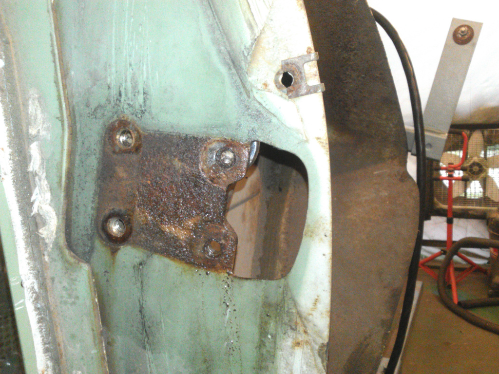
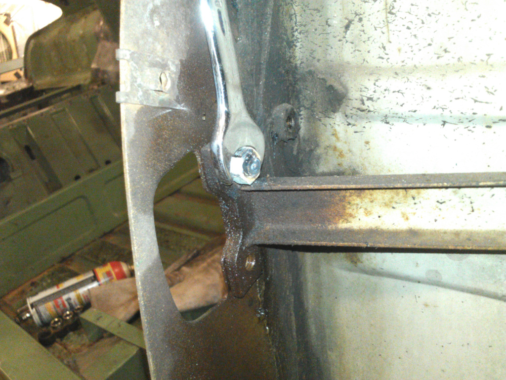
Figure 8 shows the one stubborn screw that snapped once I switched to the wrench. I didn’t want to drill the stud out so I mig welded a nut to the end of the stud which protruded a little on the back side. As shown in Figure 9, I was then able to run the broken stud out the back side. It seems heat transmitted to the stud by welding the nut to the tip, inside the nut, helped loosen it.
7. Removing Hinge Screw
8. Broken Hinge Screw
9. Removing Broken Hinge Screw
Breaking the Brake, Bending the Metal
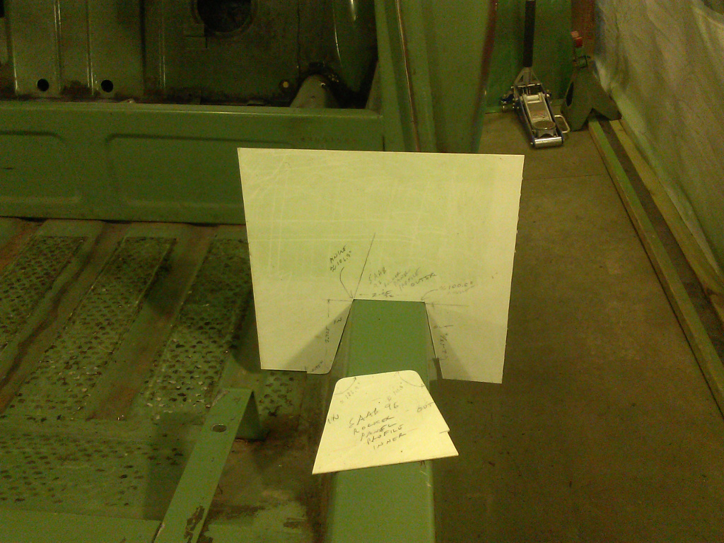
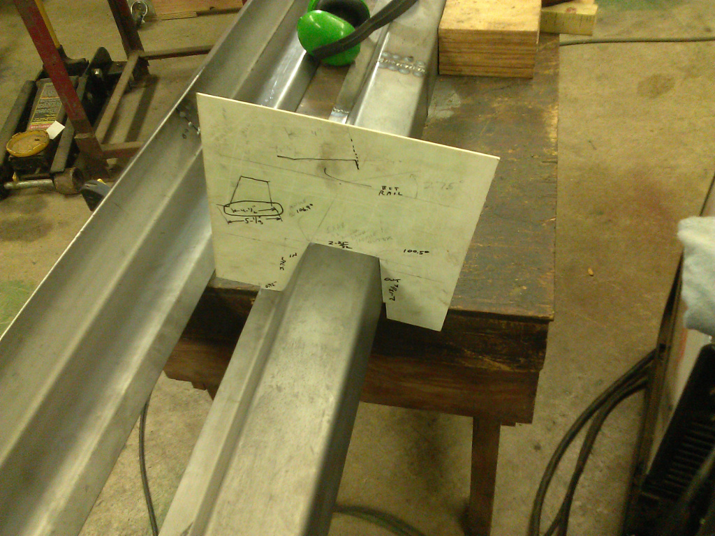
Since the rocker panels (scuff plates in Saab parlance) are nearly 6 ft long, and my inexpensive sheet metal brake can only bend 3 ft widths, my plan was to bend 3 ft sections and weld them together into a 6 ft panel. However, before bending, I decided to make a template of the profile as shown in Figure 10. I used a piece of scrap shower panel plastic. I should note that I am not good at figuring exactly where to align the metal to get bends at the desired dimension. The best advice I can give is to bend a lot of scraps until you get exactly the right profile.
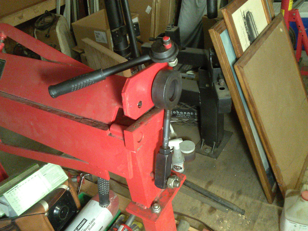
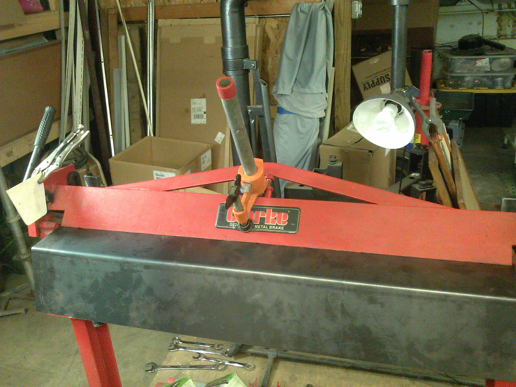
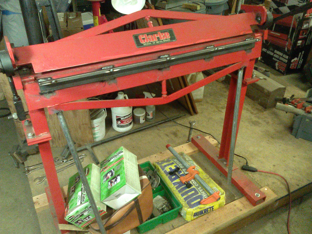
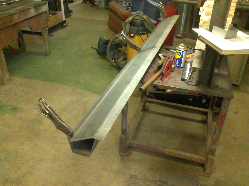
Figure 11 shows what happens when you try to bend 3 feet of 16 ga sheet metal in an inexpensive brake—broken Brake. My brake is a Clarke bought from Tractor Supply. It’s exactly the same unit that Harbor Freight sells. Not being inclined to give up, or spend money on a better brake, I reinforced the brake in key places and was able to make good, consistent bends without any bulging at the center of the sheet. In Figure 12, you can see a section set for bending, and you might notice a pipe clamp over the center. The pipe clamp keeps the upper brake plate from bowing upward when the bend is started. After the sheet is bent to the point where it is perpendicular to the upper plate, there are no more lifting forces on the plate; the force now is perpendicular parallel to the plane of the plate. I remove the clamp at this point and continue the bend. Later, the force is downward on the plate where it is supported by the brake frame. The result is a nice straight bend of constant radius. Figure 13 shows one of the finished rocker panel sections.
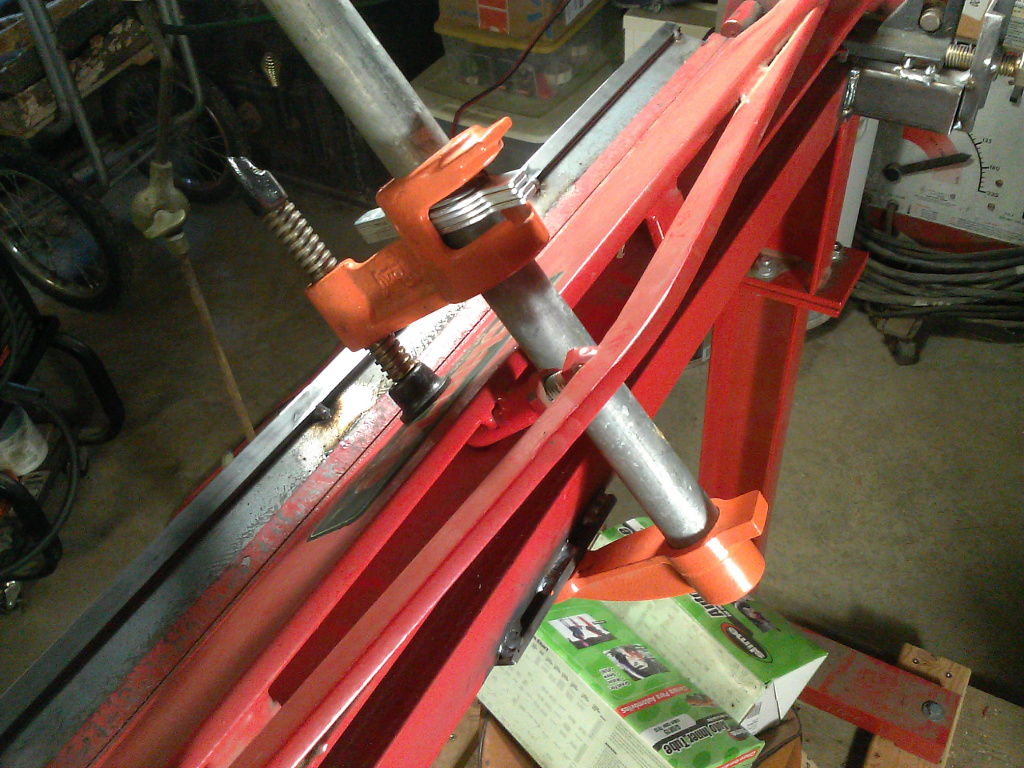
Figure 14 shows one of the improvements I made to the brake. The upper plate would slide backwards when making difficult bends because the single bolt securing the adjustment was not able to lock the stop in place, So I cobbled up an assembly for each side where I use a large bolt to prevent backward motion of the stop—very easy to adjust and very secure. Figure 15 shows the pipe clamp in place, and you may see a short flat welded to the brake frame. The flat just provides a convenient spot to fit the clamp onto.
Figure 16 shows angle iron welded to the lower plate for reinforcement and longer handles (much longer) to reduce my effort. I used 1/8″ thick by 1-1/2″ angle iron. I welded the angle iron about 1/4″ below the edge so the welds would not protrude above the edge. However, I found that large sheets would bend back a little over the 1/2″ thick lower plate. So, I welded a couple of 1/8″ by 1/2″ flats to the outside edge of the angle iron for additional support of the sheets when bending.
And, finally, Figure 17 shows an angle indicator I made of scrap shower panel plastic so I could get repeated bends of exactly the same angle. This setup worked very well.
10. Making Rocker Panel Profile Template
11. Broken Sheet Metal Brake
12. Bending a Rocker Panel Section

13. One Formed Rocker Panel Section

14. Reinforced Stop for Upper Brake Plate
15. Clamping Upper Brake Plate to Start Bend
16. Lower Brake Plate Reinforcement, Handles
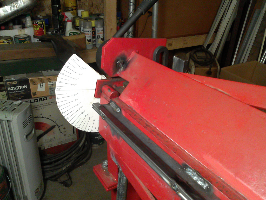
17. Angle Indicator on Sheet Metal Brake
Checking and Pickling the Formed Rocker Panel Sections
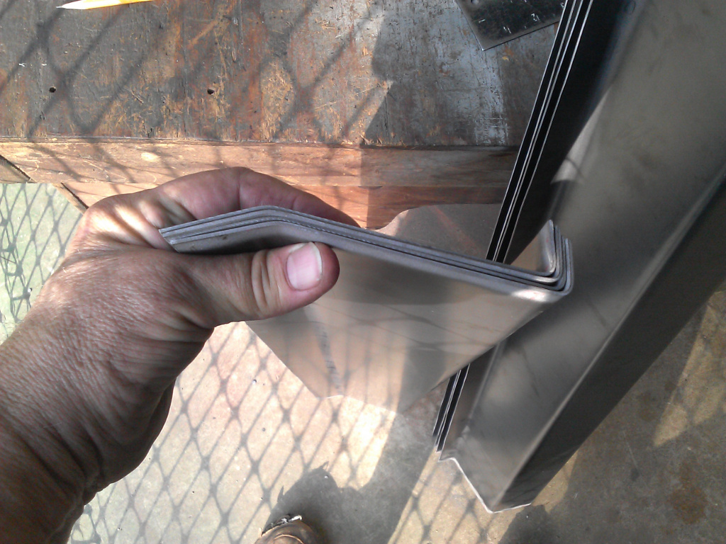
Figures 18 and 19 show the formed rocker panel bottoms and tops, respectively. You can see from the photos that the angles of bend match up very well on all sections. Figure 20 also shows how well the rocker panel bottom mates up with the rocker panel—very happy with this result.
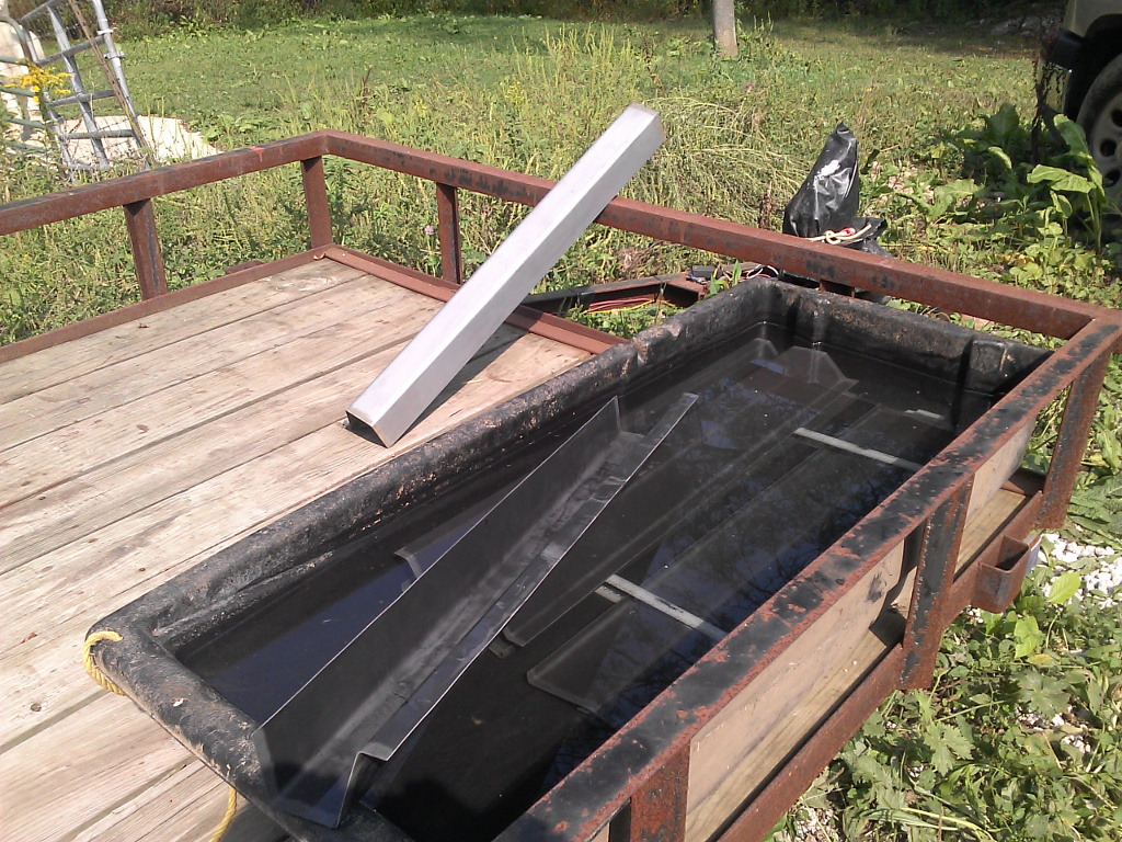
It might have been easier to clean the sheet metal of mill scale before bending, but I didn’t. My wife seems to always have a good supply of food grade, granulated citric acid on hand. So, that seemed to be the best choice for pickling the panel sections. Free, right? I cleaned out our winter alpaca manure sled to use as a tub, Googled for appropriate concentration (no longer remember), and a day later, I had nice, clean rocker panel sections, ready to weld. Citric acid works great, virtually no odor, and environmentally friendly. Do this on a hot sunny day and you can just hose the black sludge off and set the panels in the sun where they dry in minutes. Figure 21 shows the tub/sled and a rinsed panel sitting on a trailer.
18. Formed Bottom Plates for Rocker Panels
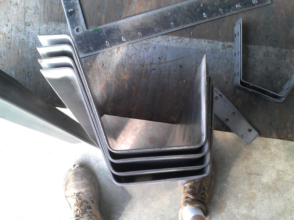
19. Formed Rocker Panel Sections

20. Testing Fit of Rocker Panel Sections
21. Pickling the Panel Sections
Welding the Rocker Panel Sections
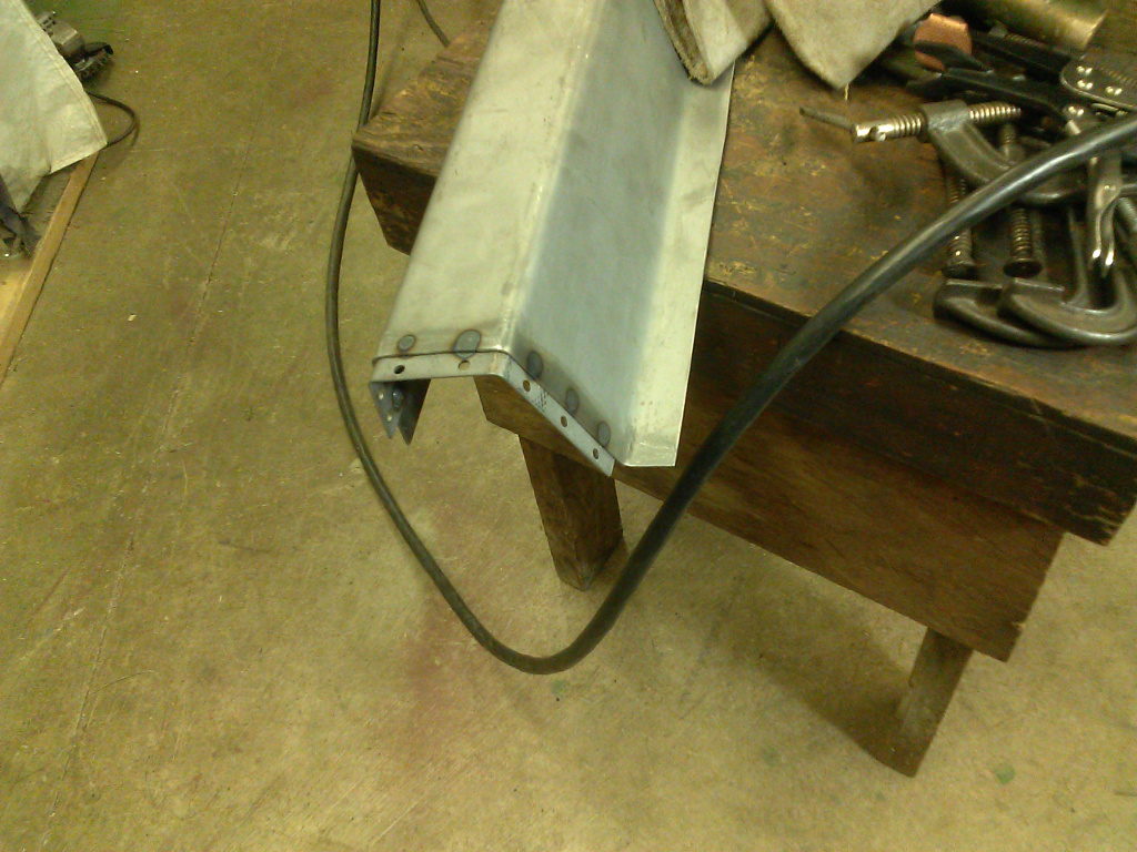
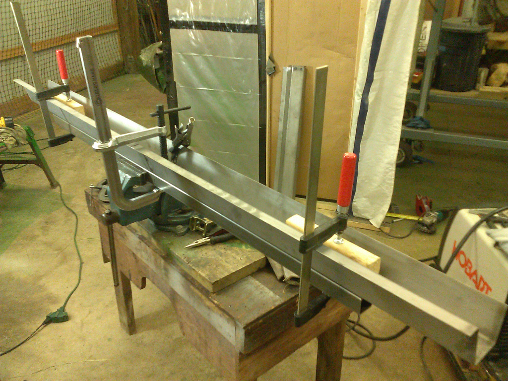
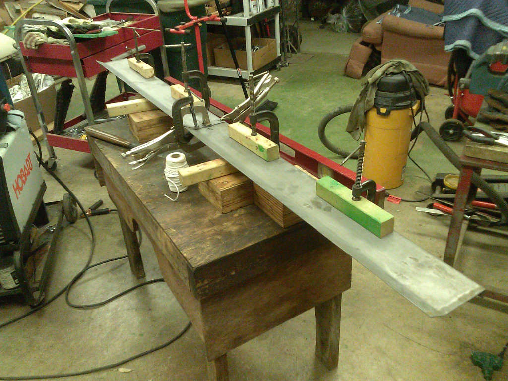
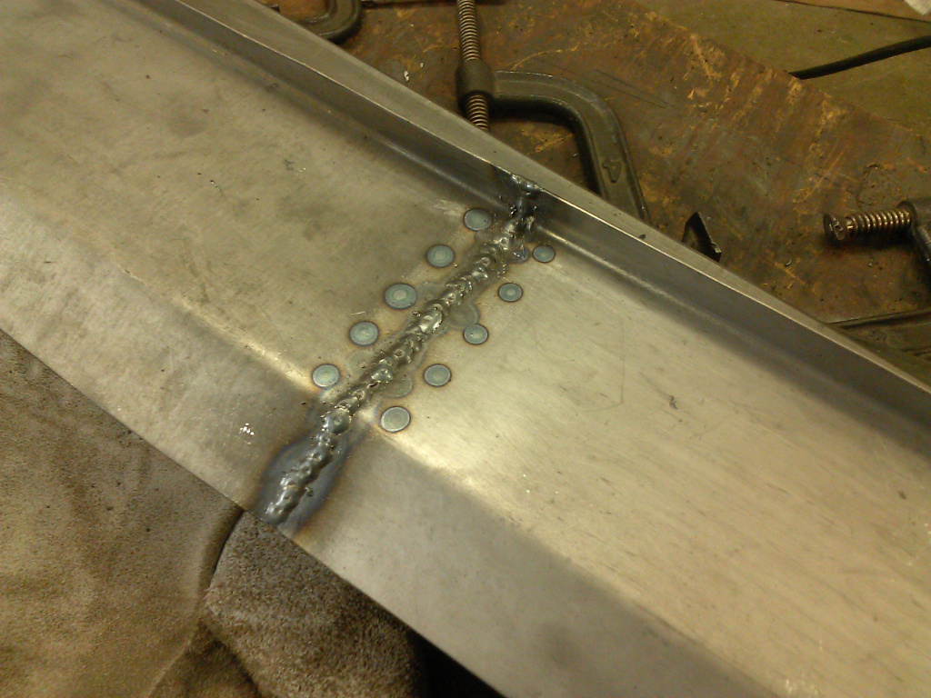
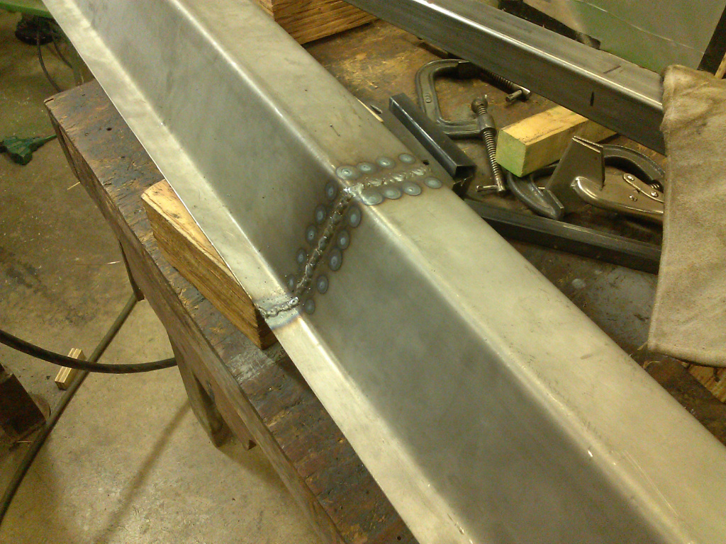
The formed rocker panel sections were now ready to join but I needed to make sure the welded joint was strong and perfectly straight at the same time. Not only that, but the profiles had to butt together perfectly so I could have a smooth, undetectable joint when finished. I decided a backing/joining strip plug welded onto one section would be the best bet. This way, I could clamp the joining section onto the strip and ensure a perfect fit. Plug welding the strip to the joining section would lock in the alignment, and I could finish welding the joint. Figure 22 shows a joining strip plug welded into one rocker panel end. Figure 23 shows the next step where two sections are being joined. I clamped both sections to a very straight piece of rectangular tubing so that I could rely on the sections staying in correct alignment while plug welding. Figure 24 shows the similar setup for two rocker panel bottom sections being joined.
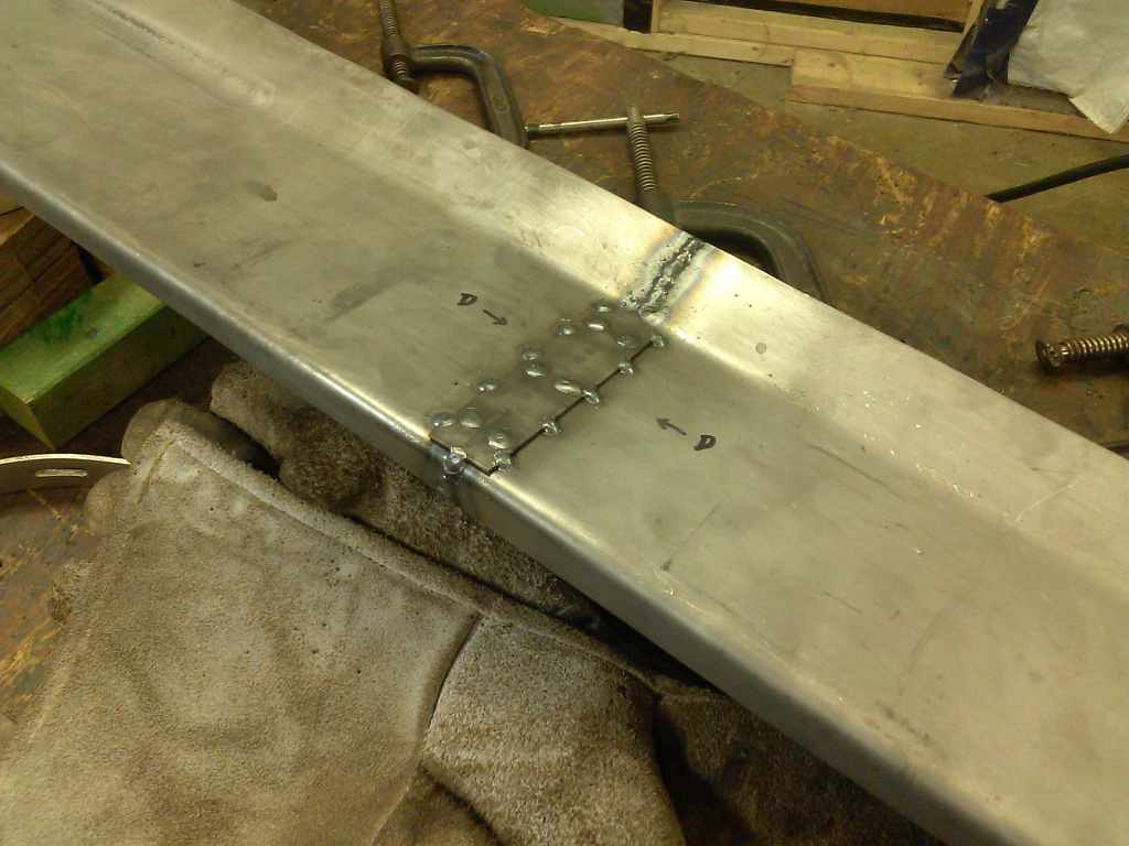
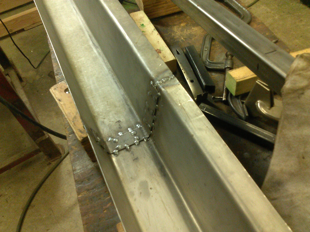
Figures 25 and 26 show the exterior and interior sides, respectively, of a welded bottom panel. Figures 27 and 28 show the exterior and interior sides, respectively, of a welded rocker panel top. These photos were taken before grinding. I only ground the exterior side of the top, for appearance sake, and welds on mating surfaces where absolutely necessary. I double checked the profile with the template as shown in Figure 29. Great fit!
22. Backing/Joining Strip
23. Welding Two Rocker Panel Sections
24. Welding Bottom Sections
25. Welded Bottom, Exterior
26. Welded Bottom, Interior
27. Welded Rocker Panel, Exterior
28. Welded Rocker Panel, Interior
29. Checking Rocker Panel Profile
The Finished Rocker Panel Sections
Figure 30 shows the final result, two new rocker panel sections, both top and bottom. Just looking at them doesn’t give a clue as to how much work went into making them! As an additional check, it is not shown here but I test fitted the stainless steel kick plates or covers that are standard on the Monte Carlo. Again, a perfect fit! One final check is shown in Figure 31 where I test fit each rocker panel bottom and its top to ensure perfect fit.
I am elated with these results. Now, I just have to figure a sure-fire method to transplant these rocker panels into the car. It should just take some proper bracing before cutting out the rusted rocker panels, and time, lots of time.

30. Finished Rocker Panels
31. Checking Bottom to Top Fit
As always, I am impressed by what you are making from scratch. Also your photos and descriptions are first rate! Thank you for taking the time to document all your procedures!
Great to see the Monte proggressing. Nice work!
As regards removing the heavy felt on the inside floor panels, I have had excellent success on both my old Saabs and my Volvo 1800 S heating that stuff with a hair dryer and then using a stiff scraper to remove the bulk of it following that up with a kerosene or mineral spirit was to remove the rest of the residue. That might help to avoid having the teeth of the oscillating tool dig into the floor sheet metal. A more passive approach.
Have you found a replacement source for that heavy patterned felt stuff?
Good job!!
There are no teeth in the oscillating tool scraper blade, very gentle, but it doesn’t work well on curved surfaces. About the felt stuff, I once found a German site that had a look-alike made with modern materials, I think for VW, but at the moment, I don’t know of any source.
Correction: “kerosene or mineral spirit wash”.