
This is a pretty big milestone for me. It has been going slowly and will continue slowly for lack of time, but I now have a solid, straight body which eliminates a lot of worry for me. The body still needs a fair amount of detail work, e.g., base of the A pillars, but it’s downhill from here. This post will be more pictures than words, but the pictures are mostly self-explanatory.
Bracing and Cutting Away Old Driver-Side Rocker
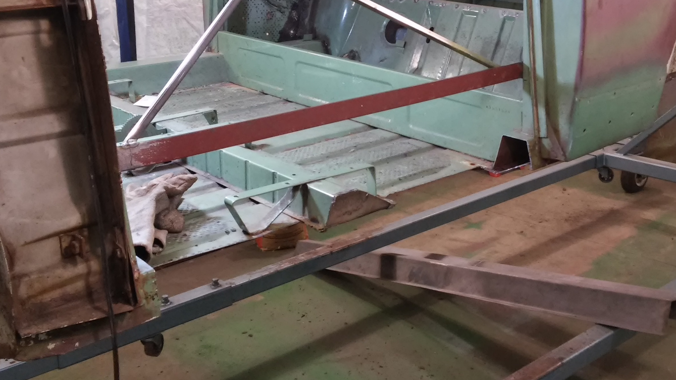
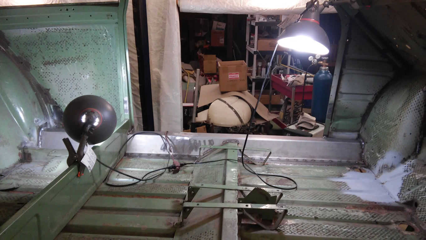
Figures 1-6 below show the process of cutting away the old rocker panel and the rusted portion of the floor. Of course, before starting, I braced the door frame because the car is on a rotisserie and I didn’t want to risk sag or any change in the door opening geometry. I used some scrap bed framing and left over 1/2″ square tubing. The bracing was tack welded in place as shown except near the A-pillar where I was able to use existing holes to bolt the bracing in place.
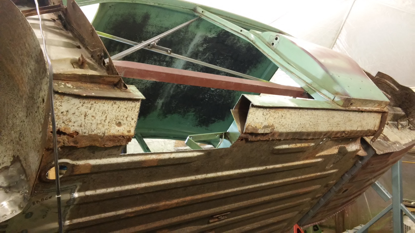
Once the bracing was in place, I drew a line on the floor to delineate the good from the bad and to guide my cuts. Virtually all cutting was done with a 1 mm cutting disk in my 4-1/2″ angle grinder. After carefully cutting the floor, I started cutting out sections of the rocker panel, a little bit at a time. I would think it is impossible to remove a rocker panel completely intact.
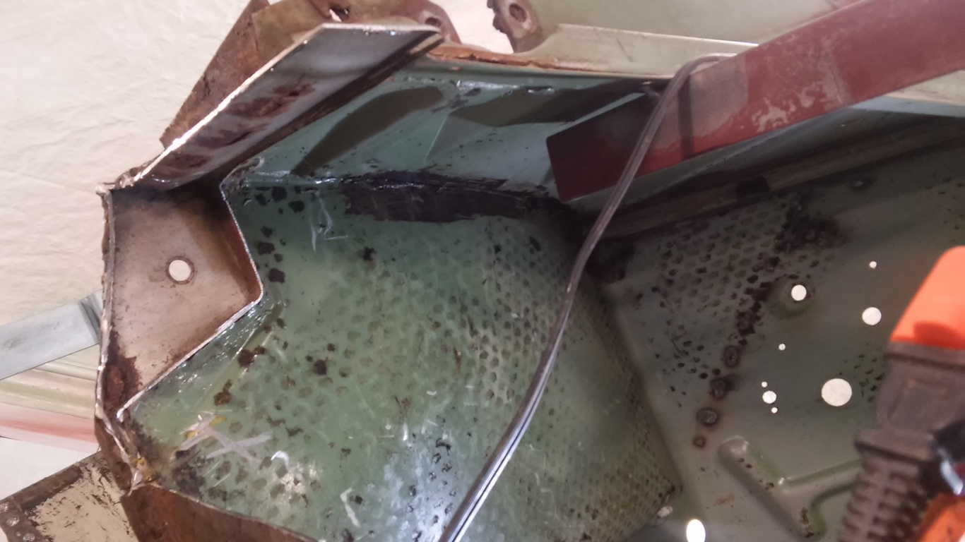
I didn’t cut too close to anything that I didn’t want to risk damaging, so I had a lot of remnants which were easy to remove by grinding. Unfortunately, rust reared its ugly head in places that I thought were solid, but repairs were easy with the old rocker out of the way. I guess this is why it is often recommended to replace rocker panels rather than to repair them; removal exposes hidden rust.
Figure 6 shows the result of cutting and grinding. All repairs to the wheel housings and surrounding areas were made at this time.
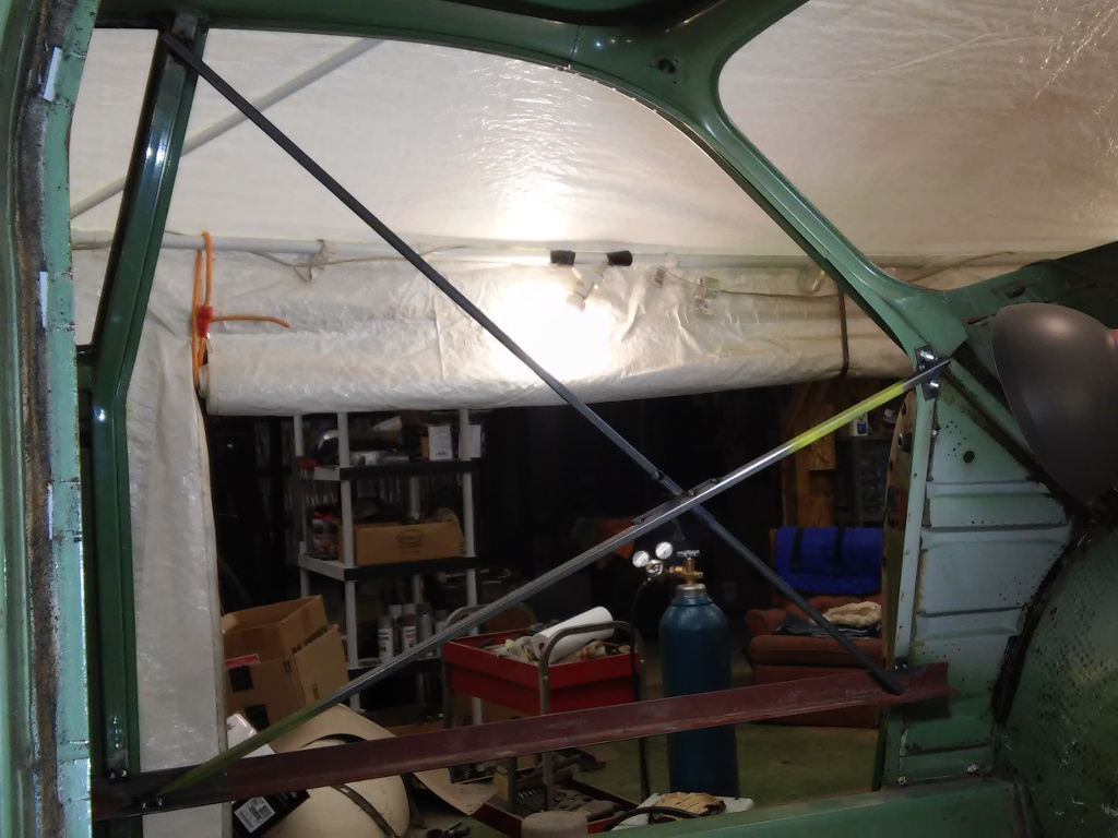
1. Bracing Driver-Side Door Opening
2. First Piecemeal Cut
3. Most of Door Section Removed
4. Remnants to be Ground Away at Front Wheel Housing

5. Grinding Remnants Exposes Rust Holes

6. Driver Rocker Completely Removed
Fitting and Welding New Driver-Side Rocker
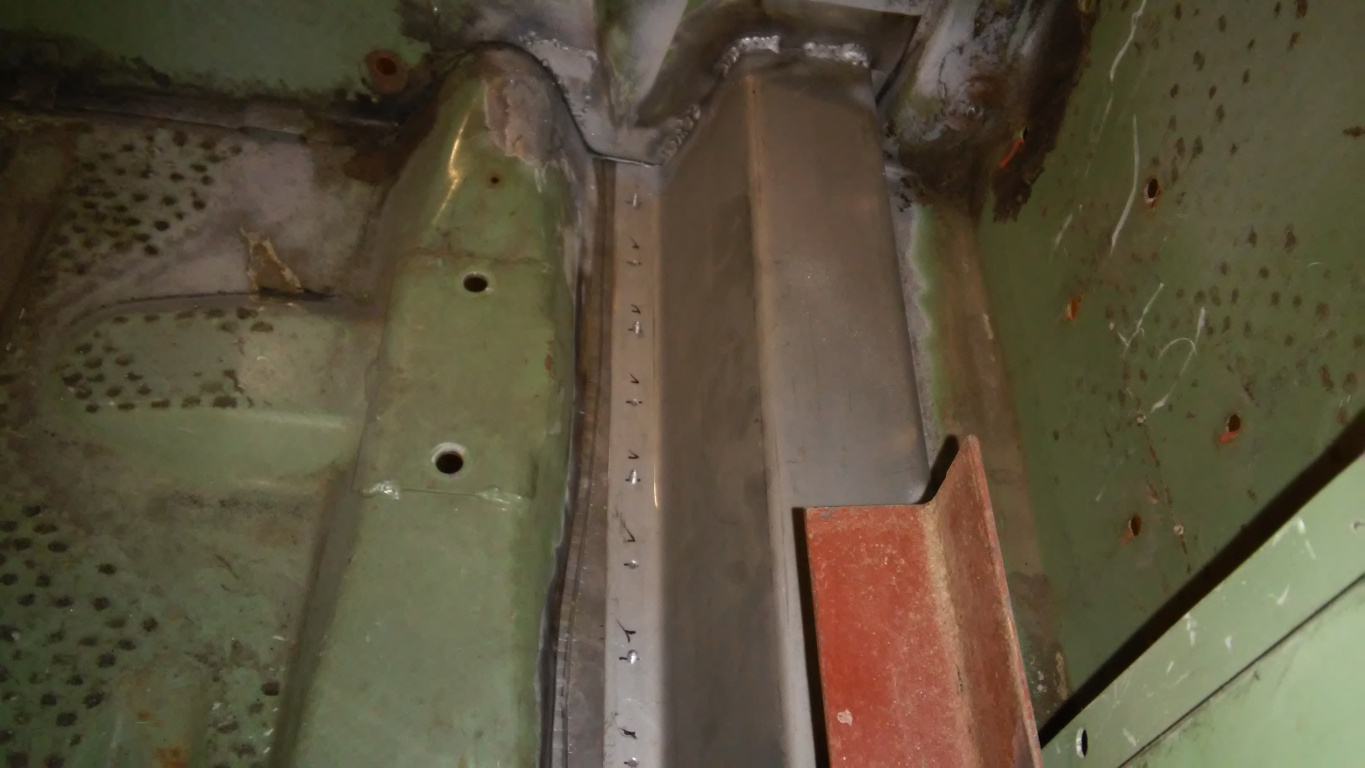
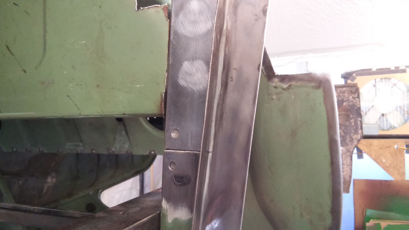
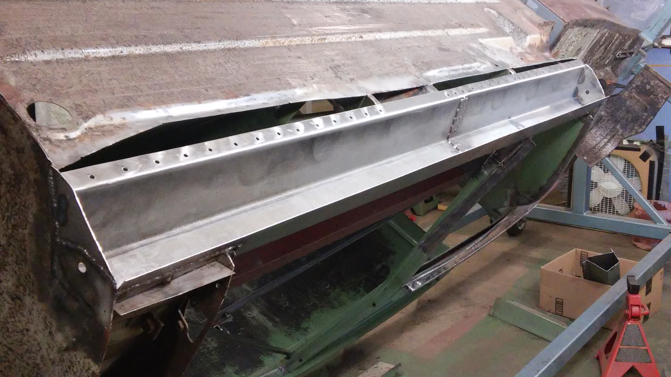
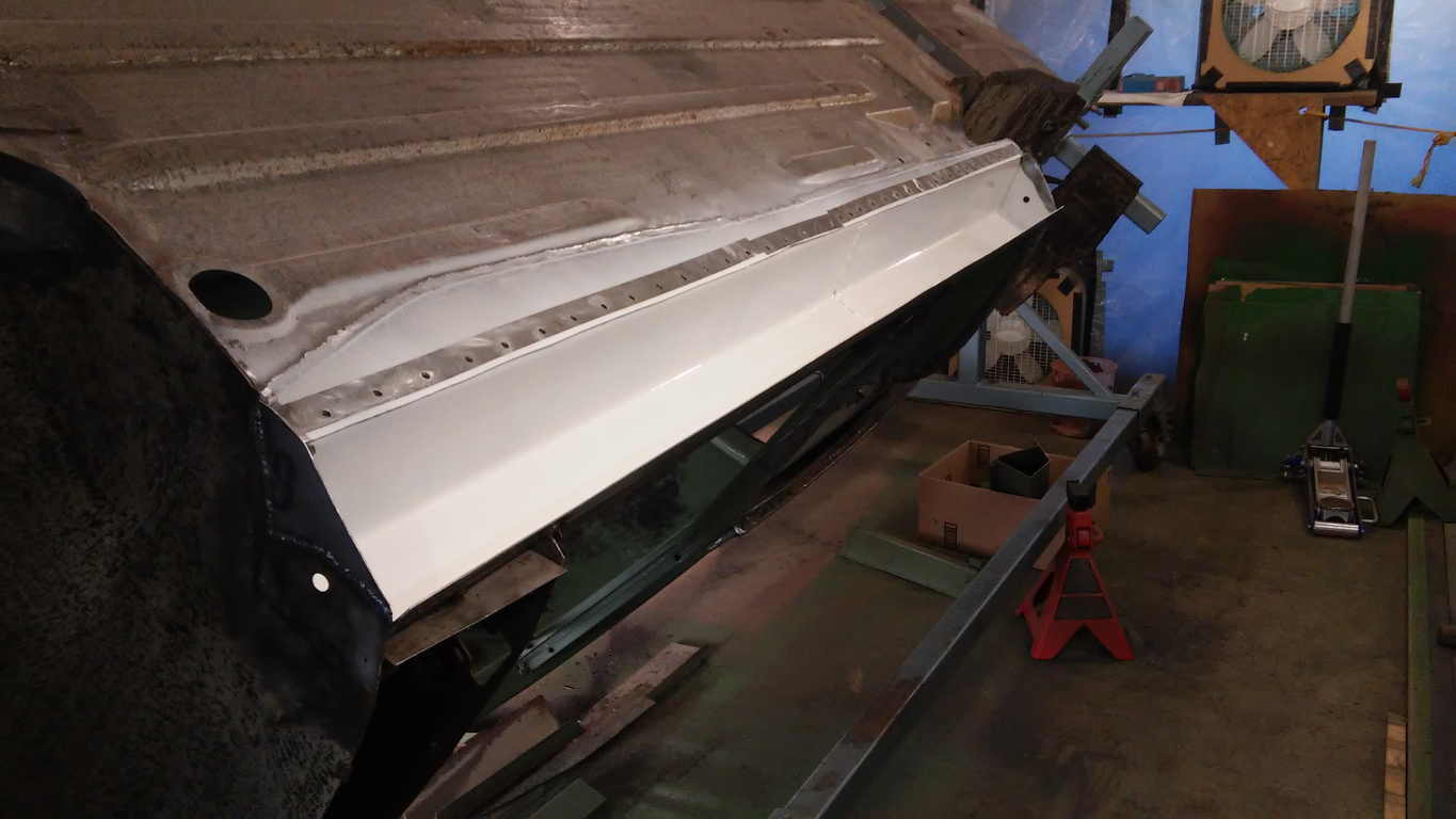
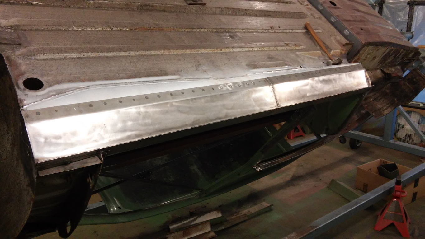
With the rocker panel removed and surrounding area repairs done, it was time to install the top half of the rocker panel. Before fitting it into place, I temporarily clamped the bottom half in place along the outer edge to make sure the top half was straight and true while welding it into place. It would have sucked if I welded the top and found later it didn’t match the bottom due to bowing. I don’t show the welding but I simply matched the factory welds as much as possible.
I think I spent 2 hours positioning, measuring and re-positioning, but just a half hour actually welding. I got it right though.
7. Driver-Side Rocker Positioned for Welding Top Half
Patching Driver-Side Floor
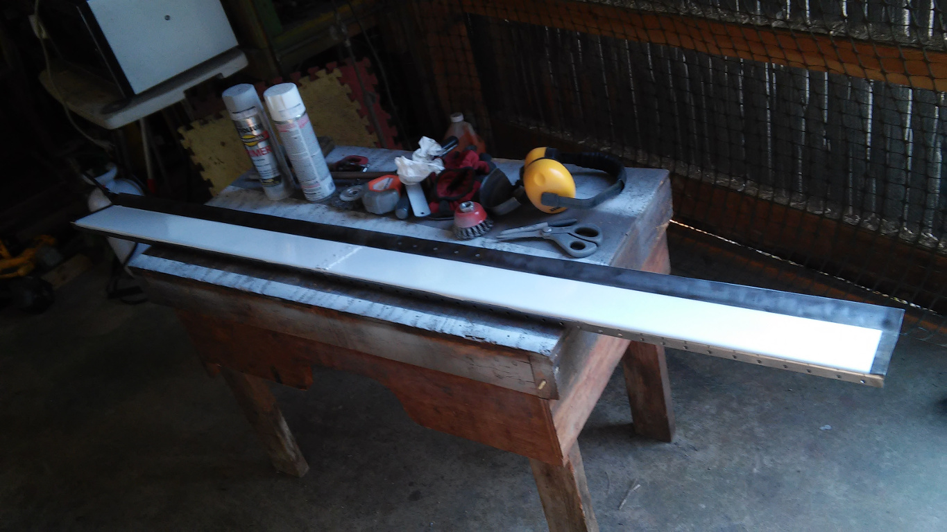
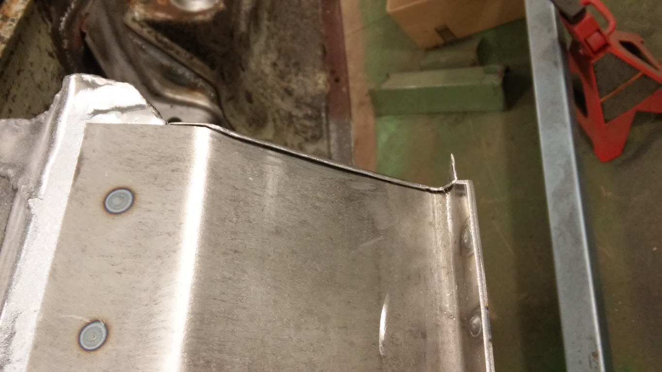
Turning my attention to the floor, I cut 18 ga sheet metal patches about 2 feet long, matching the inner edge to the floor cut line. Initially, I planned on butt welding, but after consideration, I decided to add a small flange as shown in Figure 8 for strength and to make welding easier. I screwed the floor patch to the rocker and then massaged the floor and patch into a good fit prior to welding. Figure 9 shows the first patch tack welded in place. To avoid/minimize warping, I extended each tack with 1/2 second tacks until fully welded as shown in Figure 10. After each tack, I used a blast of air to cool the weld. This method seems to work best for me for eliminating warp. Figure 11 shows the last patch at the rear being welded into place.
Once the floor patches were finished, I masked areas which required further welding, and I then applied a coat of primer and a finish coat as shown in Figure 12. I only painted areas which would be hidden later; color didn’t matter.
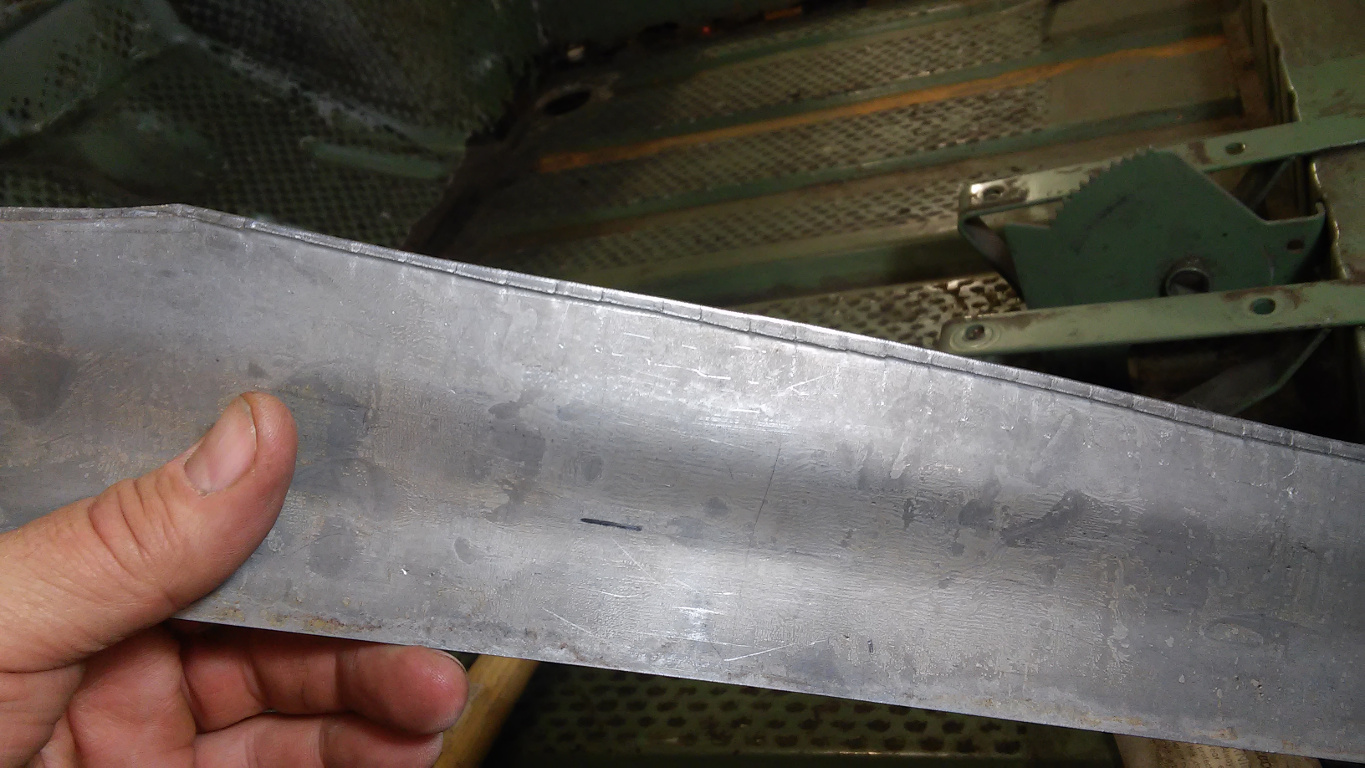
8. A Floor Patch
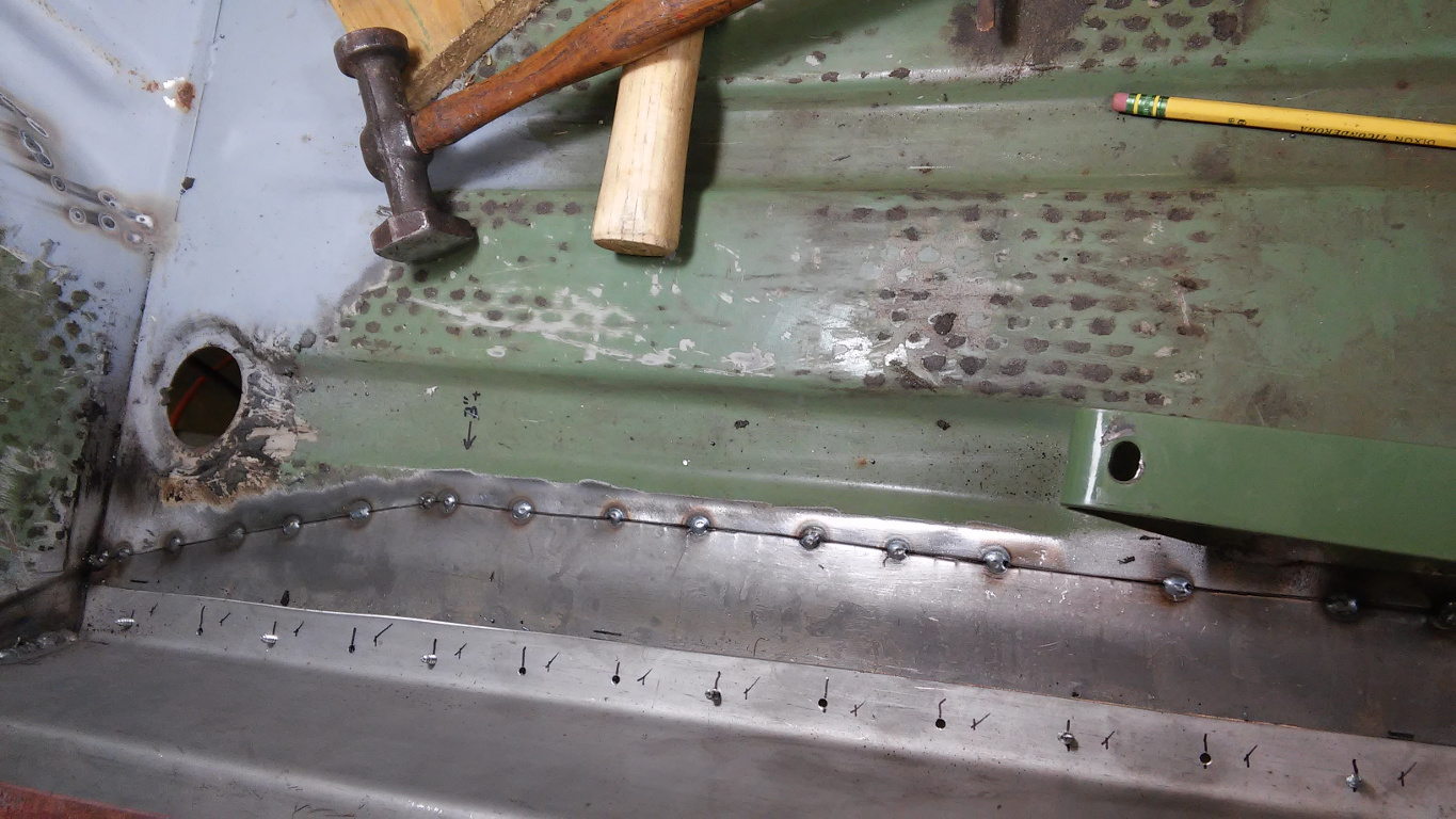
9. Floor Patch Tack Welded into PLace
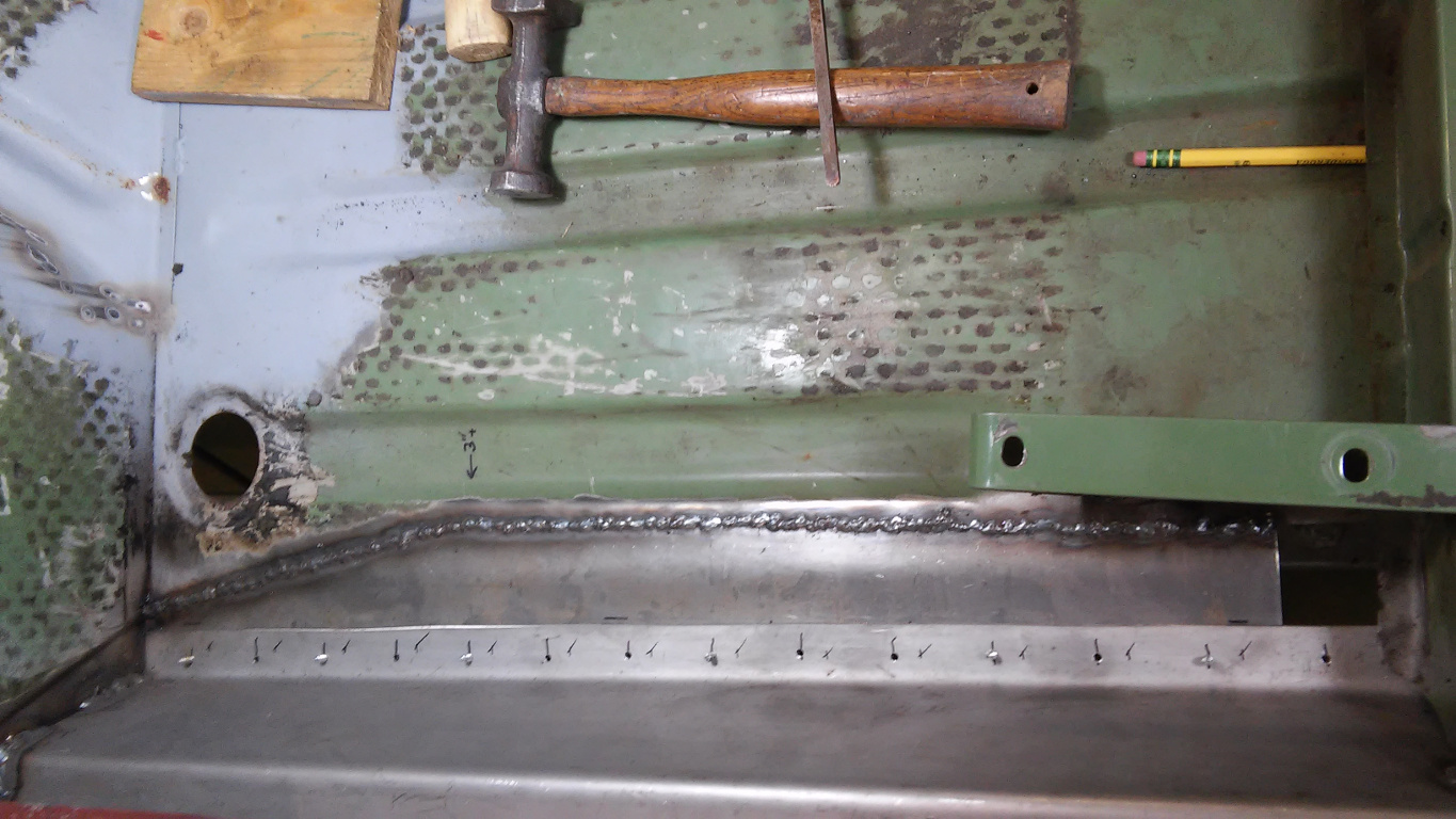
10. Floor Patch Welded in Place
11. Rear Floor Patch Being Welded
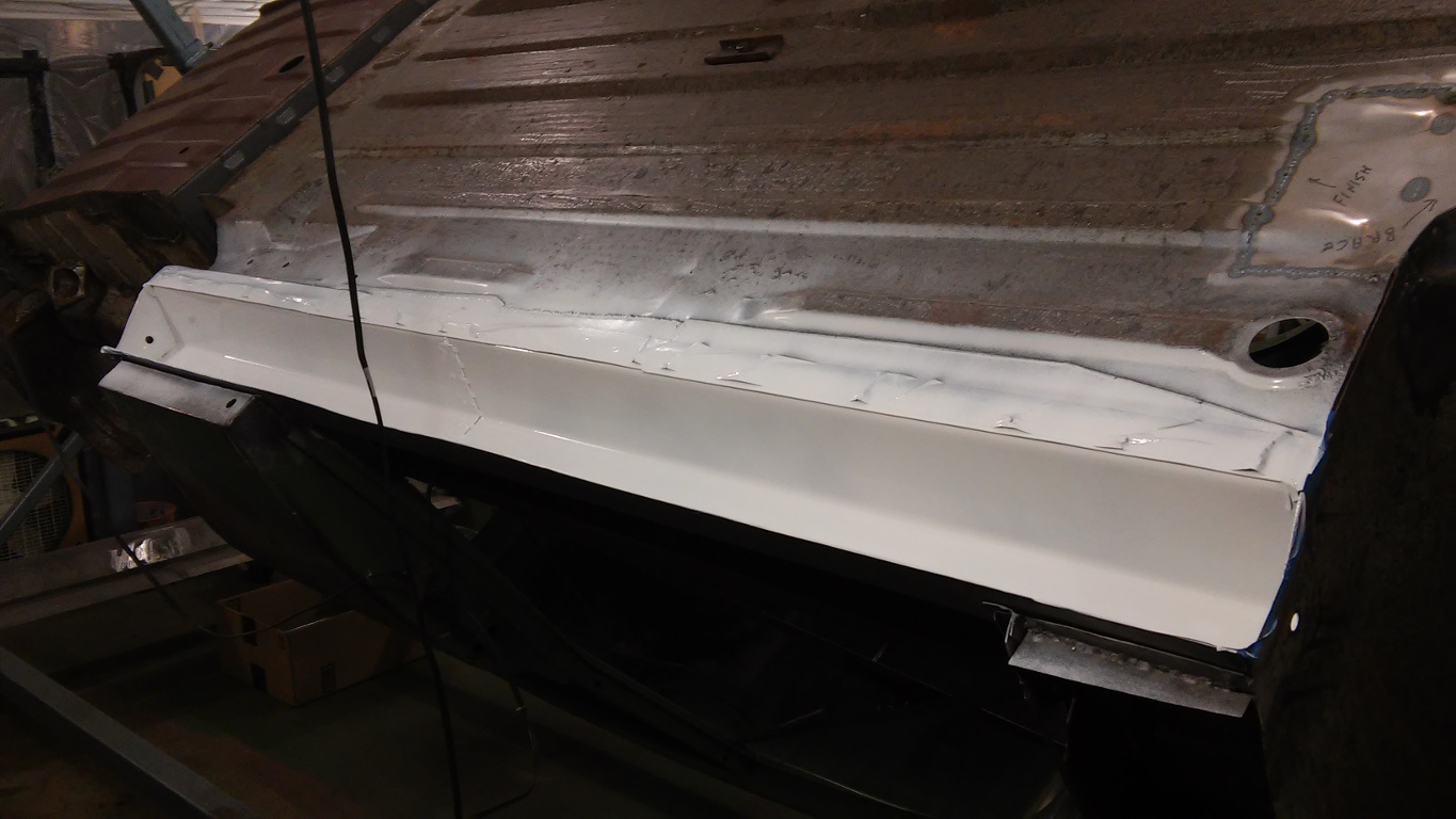
12. Masking and Painting Rocker Interior
Welding Driver-Side Rocker Bottom
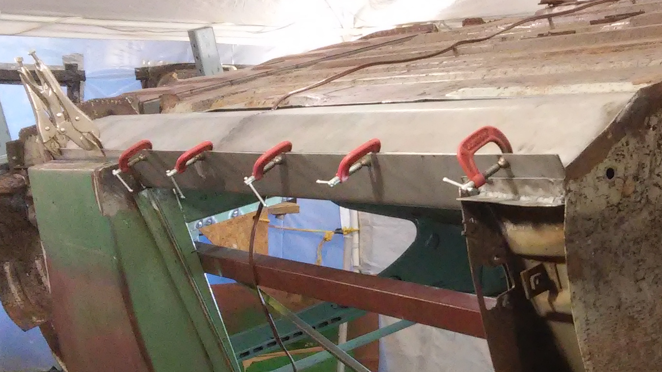
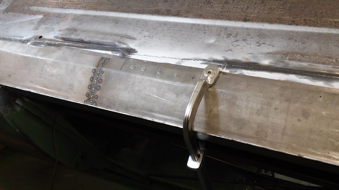
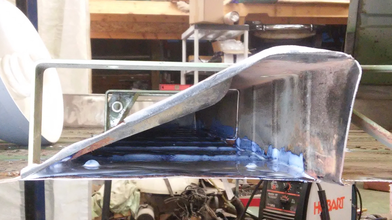
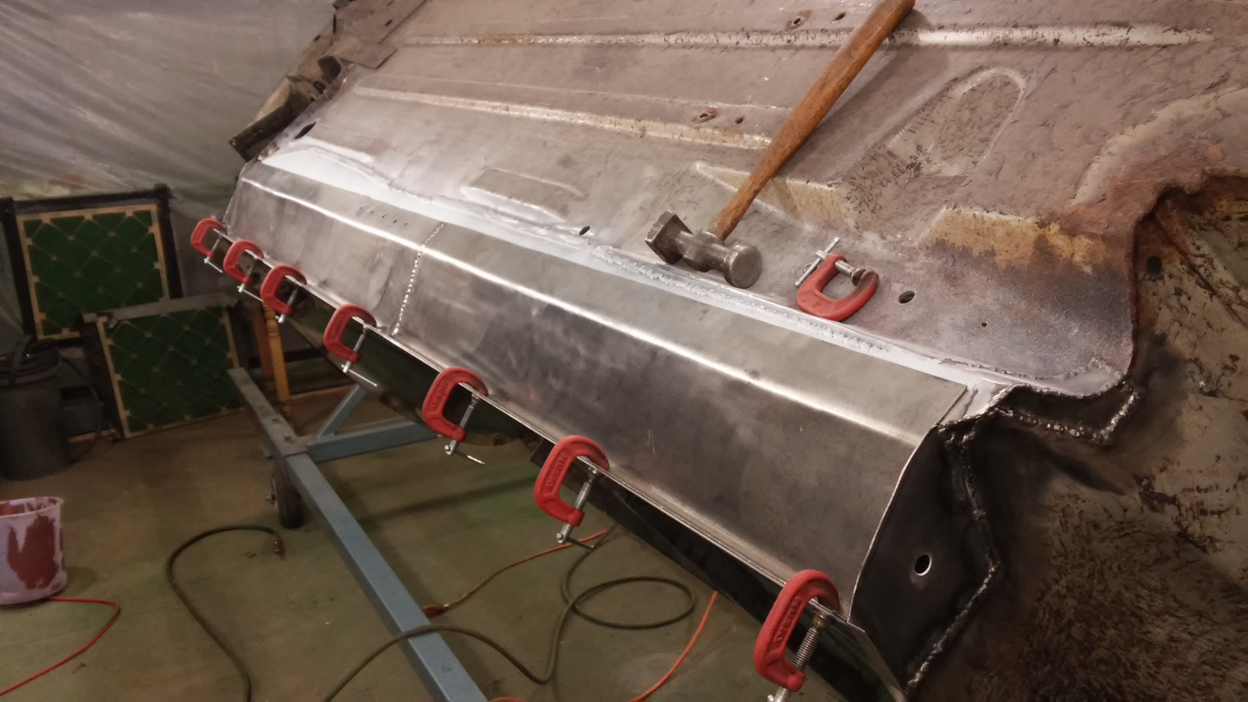
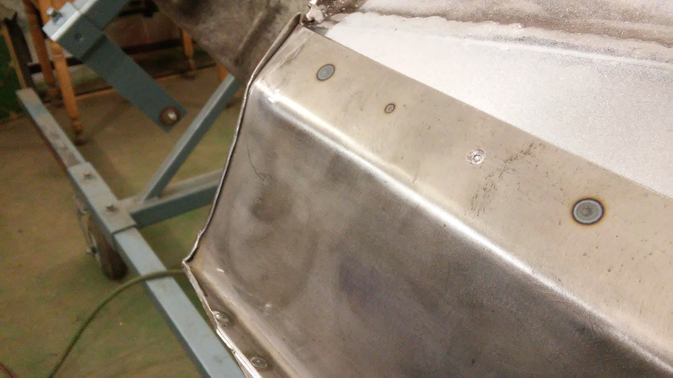
With the floor patches complete, it was time to weld the bottom of the rocker panel into place. I had painted the top side of the bottom except where welding would take place. Figure 13 shows a plethora of C-clamps to ensure a tight fit. For pocket welding, I had earlier punched holes in the outer flange of the bottom at a spacing matching the original spot welds. Figure 14 shows the pocket welds, and the heat marks in Figure 15 prove good penetration.
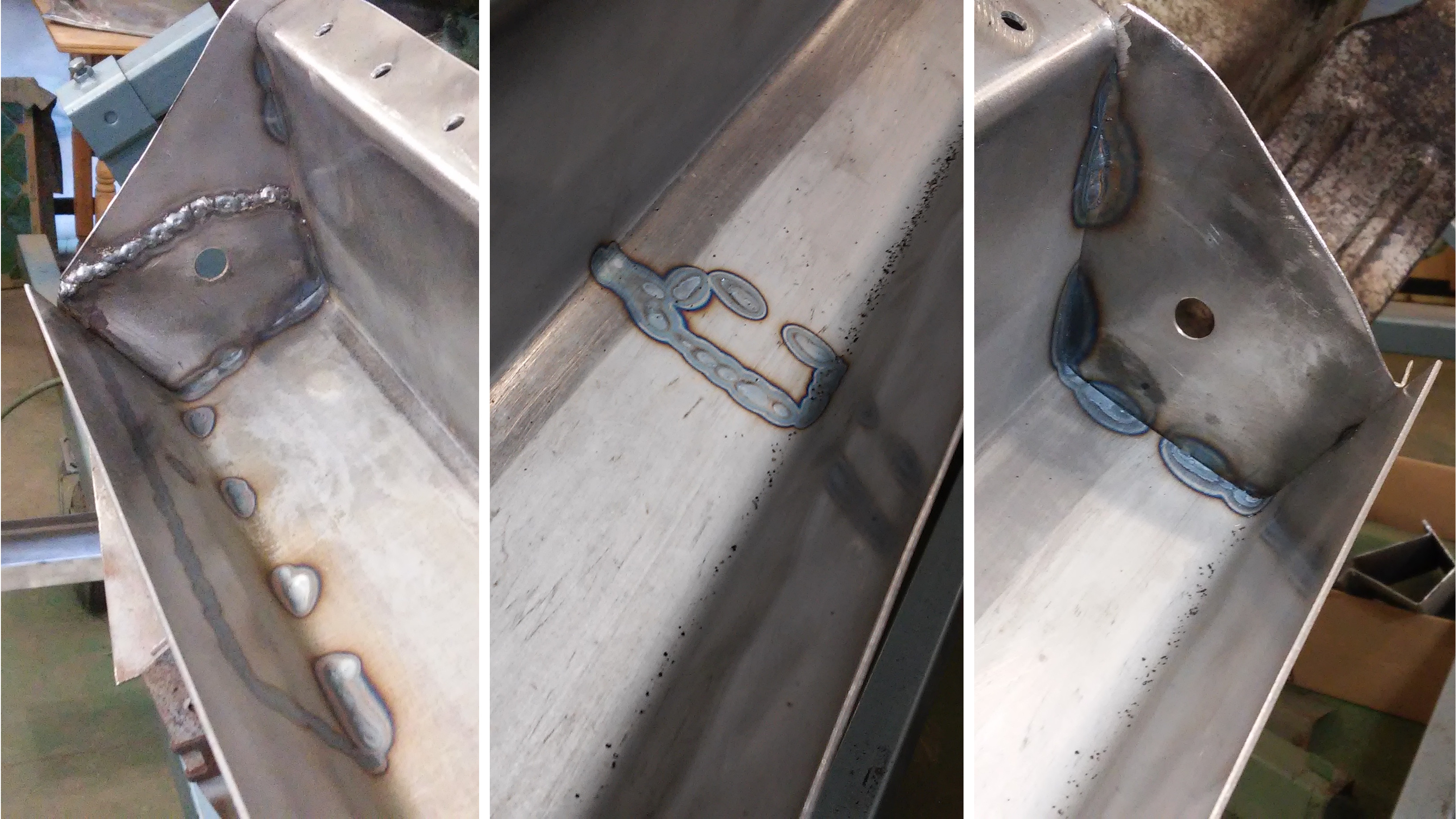
It was now time to weld the inner rocker flanges together with the floor patches sandwiched between. I had earlier drilled holes in the flange of the top half of the rocker for pocket welding. I now drilled matching holes in the floor patch so I could pocket weld through the floor patch to the rocker bottom. The only problem was the short section hidden by the cross member which supports the front seats. Here, I pre-drilled holes in the rocker bottom and pocket welded from the bottom side, using screws to clamp the rocker halves together as shown in Figure 16.
I used a massive C-clamp elsewhere to clamp the rocker halves while pocket welding from the top. See Figure 17.
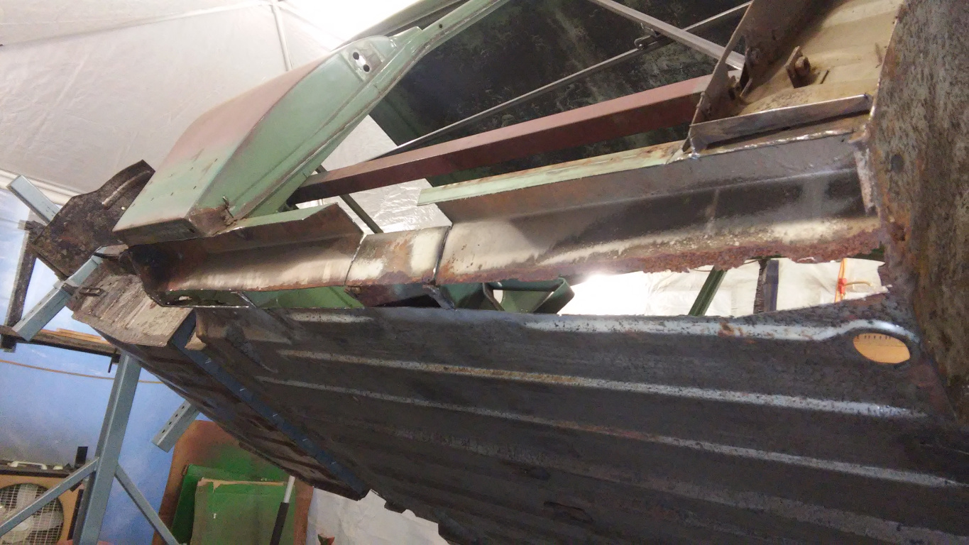
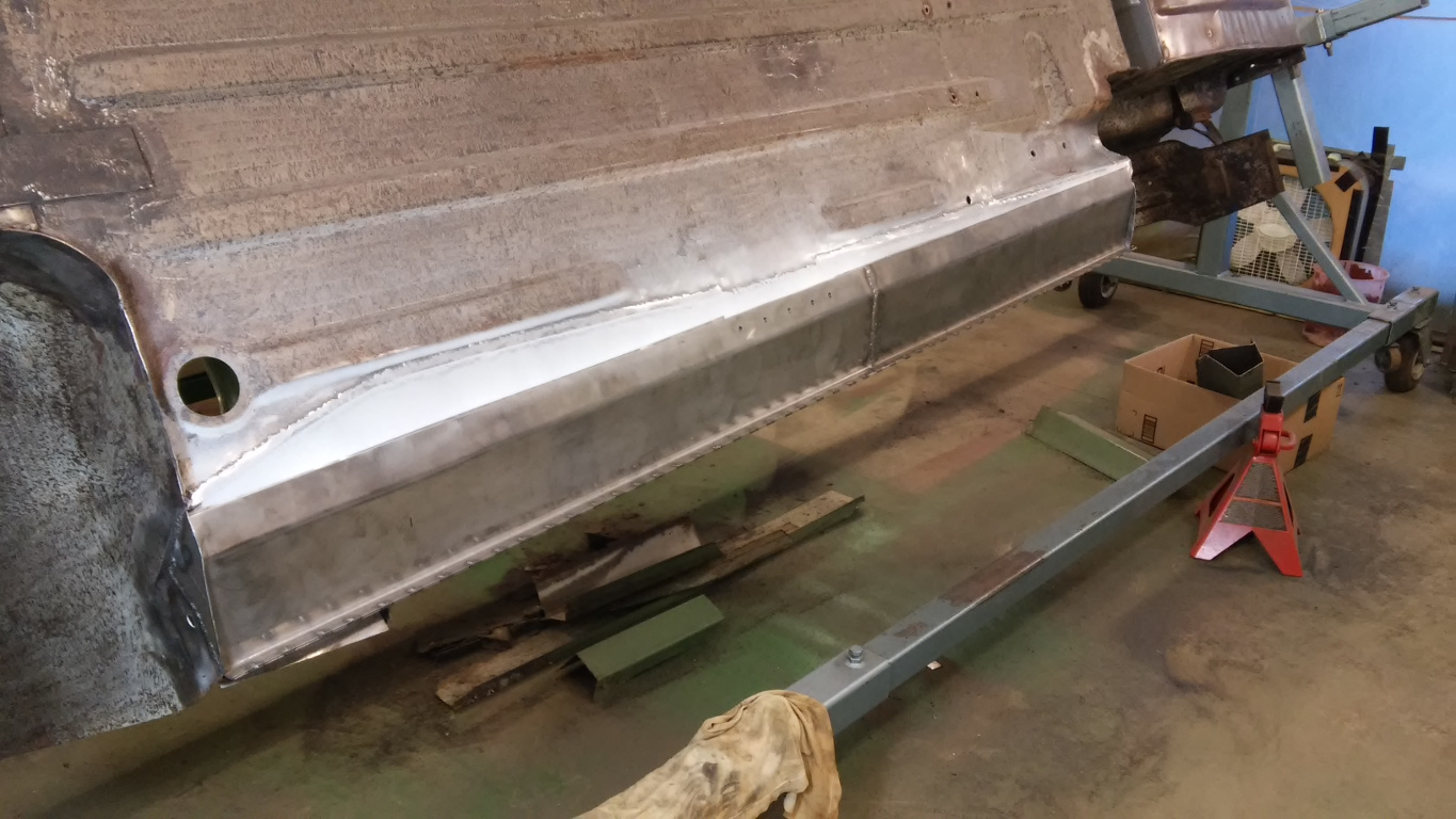
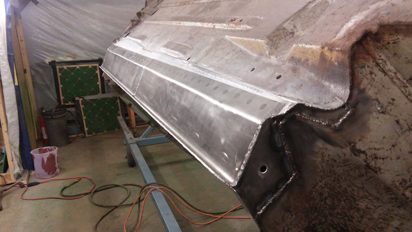
With the flanges welded, I trimmed the bottom flange, fit the wheel housing to the bottom ends, and welded just like the factory original as much as possible. See Figures 18-20. Figure 21 shows the nice tight fit from the underside. In Figure 22, I was finishing up some welding where the rear seat support meets the rocker panel.
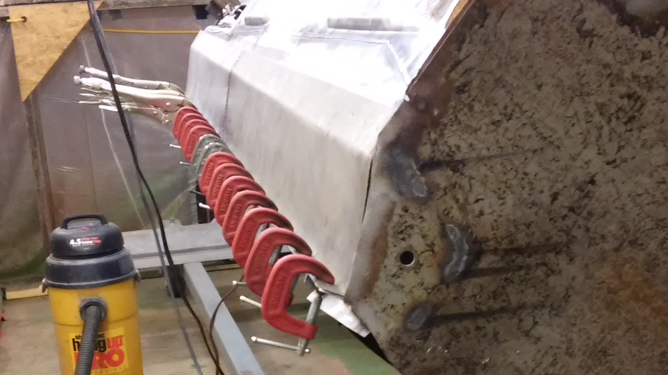
13. Rocker Bottom Half Clamped for Welding

14. Bottom Rocker Half Pocket Welded to Top
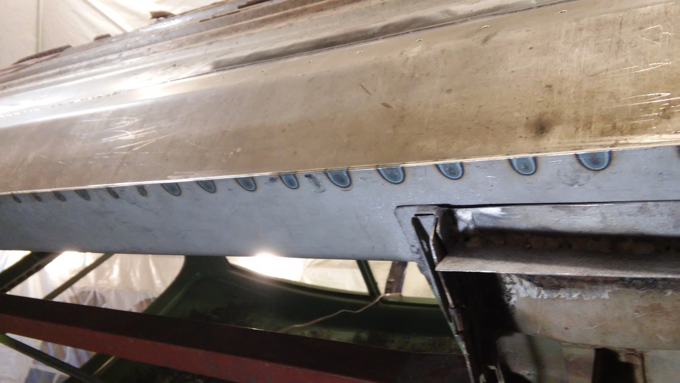
15. Heat Marks Prove Good Penetration
16. Welding Under Seat Cross Member Area

17. Large C-clamp Clamping Rocker Halves for Welding
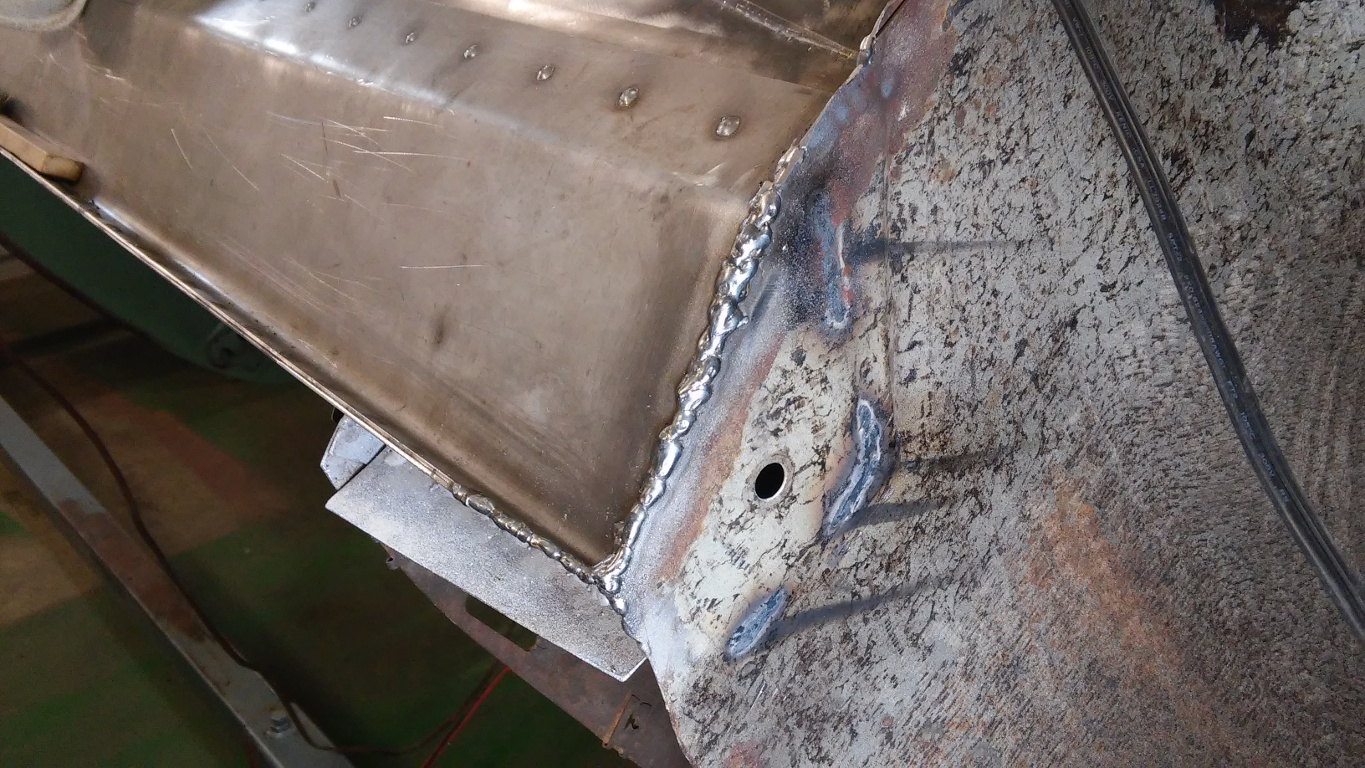
18. Rocker Trimmed, Fit, Welded at Front

19. Rocker Welded to Front Side Wall
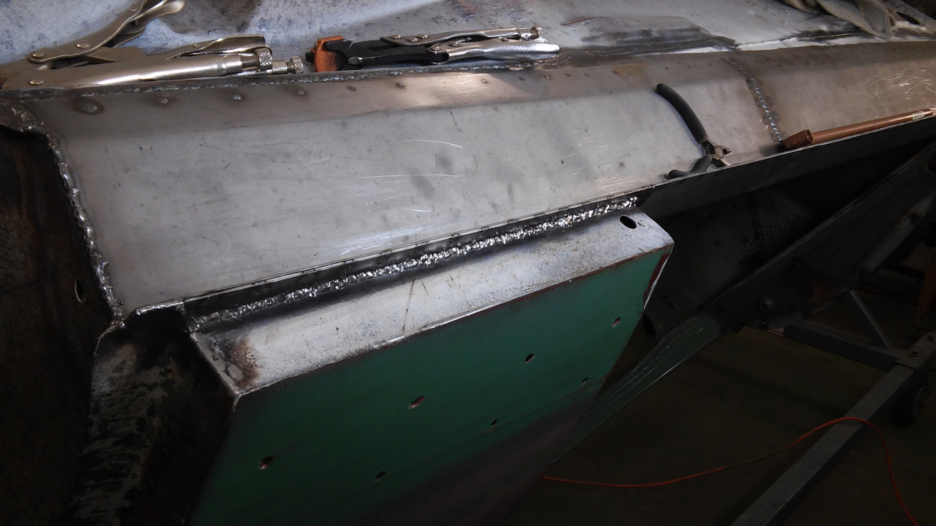
20. Rocker Trimmed and Welded at Rear
21. Tight fit of Rocker from Underside
22. Welding Rear Seat Cross-member to Rocker
Cutting out Passenger-Side Rocker and Making Patches
Figure 23 shows the passenger-side rocker panel being cut. I used a little different technique here from what I learned on the driver side. Whatever is easiest is best.
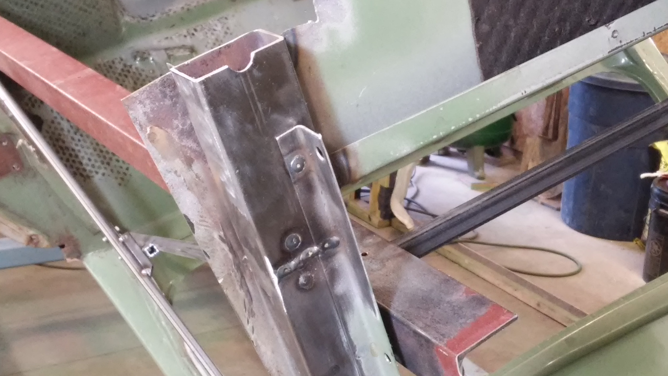
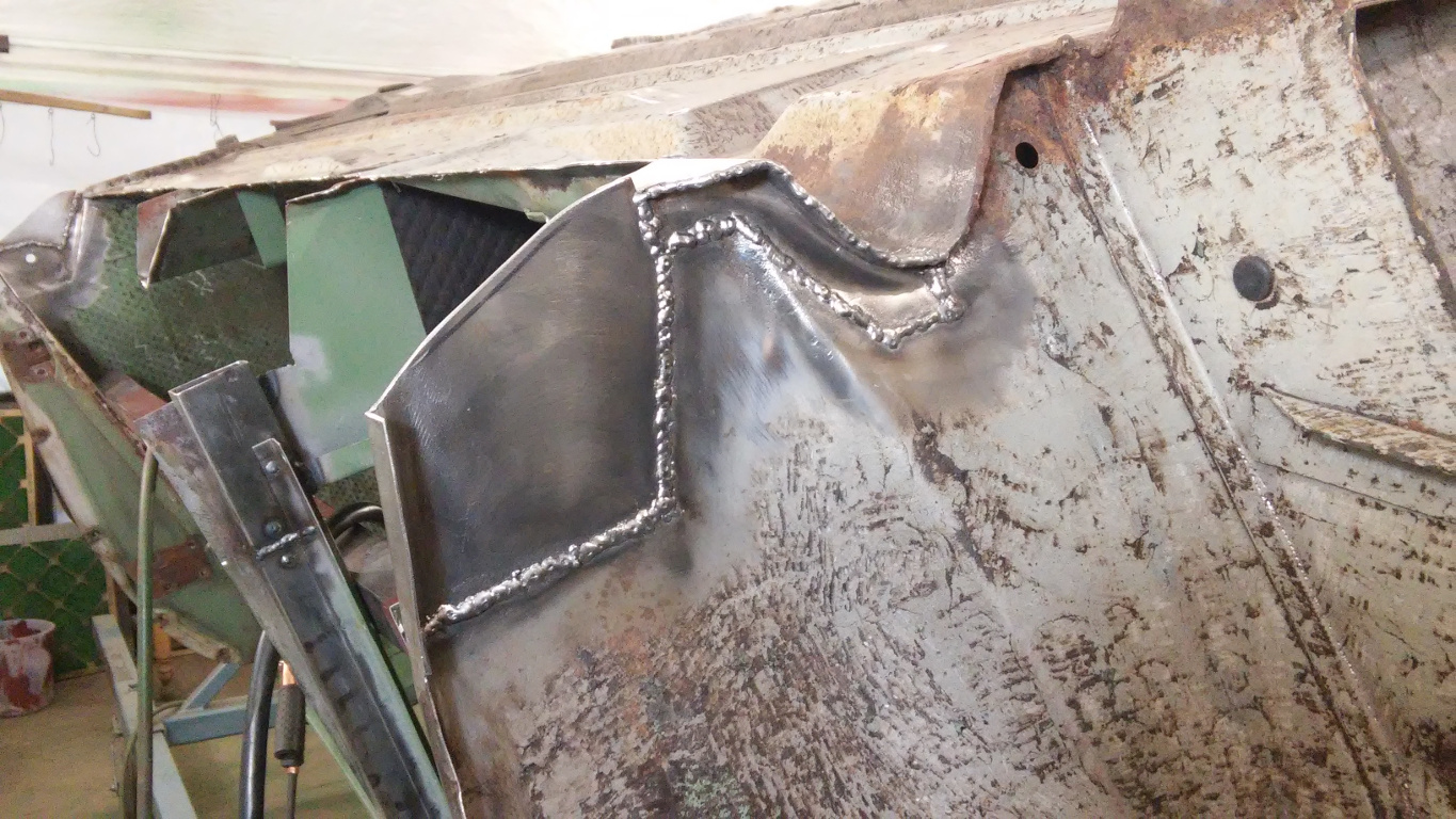
Figures 24-27 show a problem I didn’t have on the driver side. The bottom of the B-pillar had rusted and was weak. I want a safe car so I cut off approximately the bottom 4 inches. Before cutting, however, I added bracing from the passenger-side pillar to the driver-side pillar because the rear seat support no longer secured the pillar sideways. I used a good section from the donor car, and I made a tubular inner reinforcement to make a strong joint as shown in the figures.
Figure 28 shows a large patch at the rear wheel housing.
23. Cutting the Passenger-Side Rocker
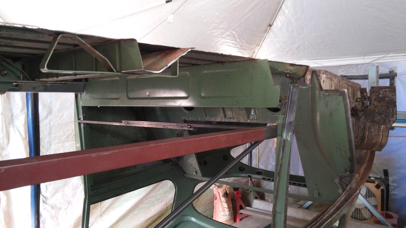
24. Passenger-Side B-pillar Cut and Braced
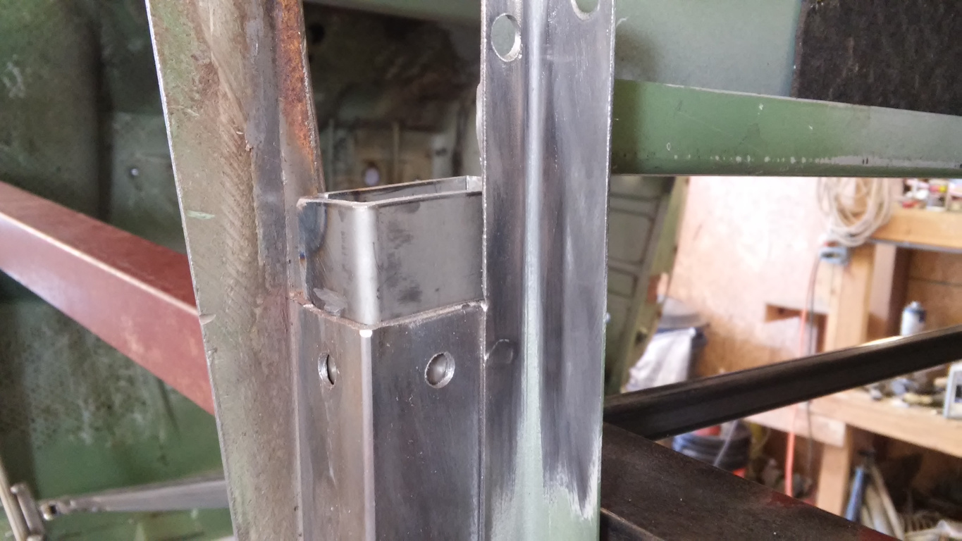
25. B-pillar Reinforcement
26. B-pillar Patch Welding
27. Finished Passenger B-pillar Patch
28. Patch to Rear Wheel Housing
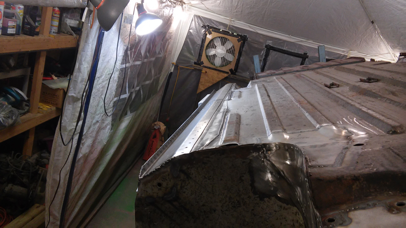
Rust Proofing Inside Front Cross Member
Because the inside of the front cross member (front seat support) would be hard to access later, I decided to do some rust proofing while it was still exposed from one end. It was solid but I wanted the extra insurance. Figure 29 shows the makeshift sprayer. I just used a garden sprayer, and I made an extension tube so I could reach through to the other side, The product is Corroseal which includes a primer in addition to the rust converter. The process was sloppy but it worked as shown in Figure 30.
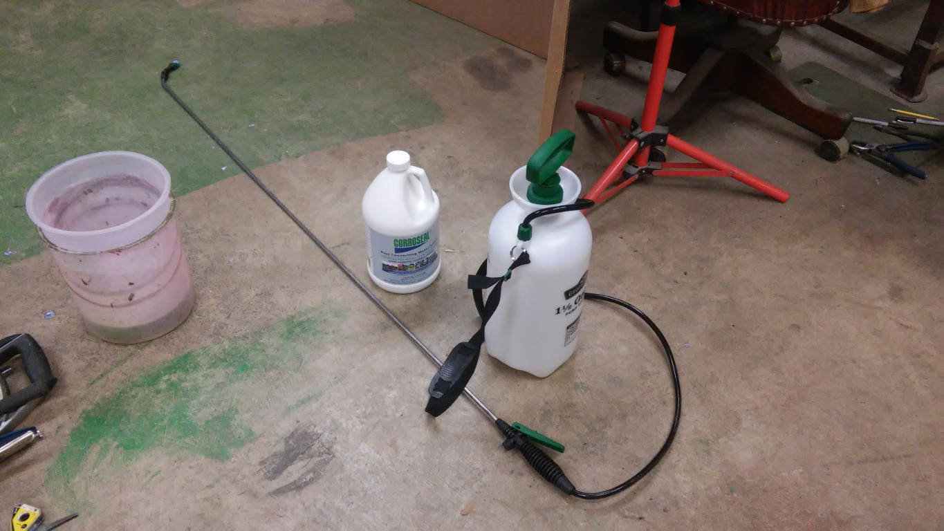
29. Garden Sprayer and Corroseal
30. Corroseal Applied to Cross Member
Finishing up the Passenger-Side Rocker
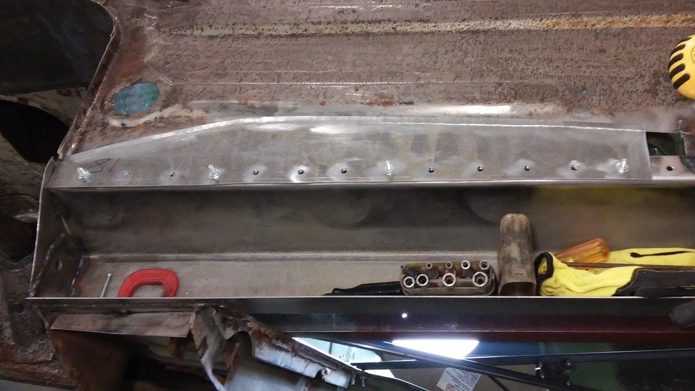
The rest of the passenger-side rocker replacement went pretty much like the driver-side rocker. For that reason, I have just dumped the photos below without explanation.
I should note two things, however. First, these photos show the pre-punched and pre-drilled holes a little better. I punched and drilled any holes before installation. The second thing you might notice is that the passenger-side quarter panel disappears during the process. That’s because I decided it was in poor enough shape that a donor would be the best bet. Removing it made clamping and welding easier.
I will cover the quarter panel replacement in my next post.
31. Welding Top Half of Passenger-Side Rocker
32. Heat Marks Showing Good Weld Penetration
33. Fitting Passenger-Side Floor Patch

34. Finishing Passenger-Side Floor Patches
35. Painting Inside of Passenger-Side Rocker
36. Painting Inside of Passenger-Side Rocker Bottom
37. Welding Passenger-Side Rocker Bottom
38. Passenger-Side Rocker Outside Flange Welded
39. Passenger-Side Rocker Floor Flanges Welded
40. Grinding and Trimming at Rear Before Welding
41. Grinding and Trimming Rocker Front Before Welding
42. Finished Passenger-Side Rocker
Excellent work. Keep it coming.