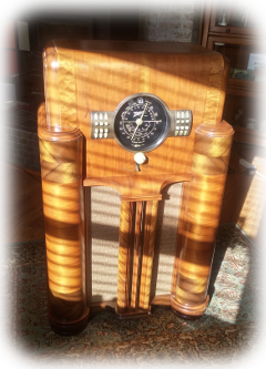
1939 Zenith Radio Restoration
 My wife and I have a 1939 Zenith console radio, model 7s363, which had been sitting in a
hallway corner, unused, gathering dust for 48 years or thereabouts. This is the story of its successful complete restoration. It's a long photo documentary (with a link to a video) but it might be worth reading by someone considering a similar, first-time restoration. Click on the image to read the documentary.
My wife and I have a 1939 Zenith console radio, model 7s363, which had been sitting in a
hallway corner, unused, gathering dust for 48 years or thereabouts. This is the story of its successful complete restoration. It's a long photo documentary (with a link to a video) but it might be worth reading by someone considering a similar, first-time restoration. Click on the image to read the documentary.
A DIY Antenna Amplifier for the AM band, 0.5-30 MHz
 Because of the noisy electrical environment in our home, I had to bring a long wire attic antenna signal down to the radio through a 100 foot 75 ohm coax cable. And then, because the cable was apparently a lousy impedance match to the long wire antenna, I didn't get a usable signal at the radio. So, I experimented with antenna amplifier circuits I found online that worked with the AM broadcast range, 0.5-30 MHz. Unfortunately, these all failed due to saturation caused by strong electrical interference. I then resorted to designing and making my own noise-tolerant antenna amplifier.
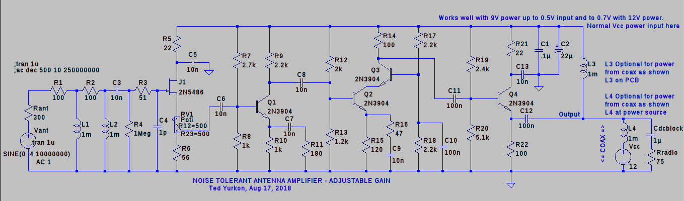
My goal was to provide an amplifier of manually variable gain so that it could be adjusted to local signal strength requirements. Additionally, I wanted it to attenuate signals below 500 kHz and above 30 MHz, essentially the tuning range of my 3-band Zenith radio. Because the most significant noise in our home was of a low frequency, I designed the amplifier with a second order high pass filter to strongly attenuate low frequency noise below 500 kHz. I further decided to use inductor coils in the high pass filter, thinking that shunting low frequencies on the long-wire antenna to ground would forcefully damp low frequency oscillations on the antenna. I added a first order, capacitive, low pass filter to attenuate noise above 30 MHz. The circuit features a high impedance input for a long-wire antenna and a low impedance output for a 75 (or 50) ohm coax cable. Each amplifier stage utilizes bias resistors to forcefully center the bias voltage between the upper and lower limits. This minimizes the risk of saturation due to strong input signals or noise.
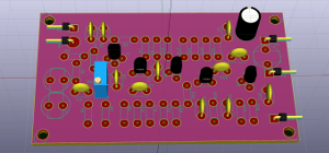
I used the freely available LTspice circuit simulator to perform test simulations the circuit design. This excellent simulator can be downloaded from https://analog.com/en/design-center/design-tools-and-calculators/ltspice-simulator.html. I used KiCad to design the printed circuit board (PCB). Many Linux distributions include this software in their repositories. Alternately, and for other operating systems, it can be downloaded from http://kicad-pcb.org. Most components are of a generic nature and can be sourced from many places. The gain control RV1 is a Bourns 3296 Trimming Potentiometer or equivalent.
Right-click on the image and select Save to download a zip file of the KiCad and LTspice file folders. The LTspice folder contains the LTspice files, and the KiCad folder contains the KiCad files used to design the PCB. A Readme.txt file is included with minimal instructions.
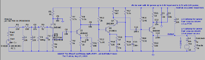 Click on the schematic thumbnail image on the left to see the LTspice schematic.
 Click on the schematic thumbnail image on the left to see the LTspice schematic.