Disassembly and Evaluation
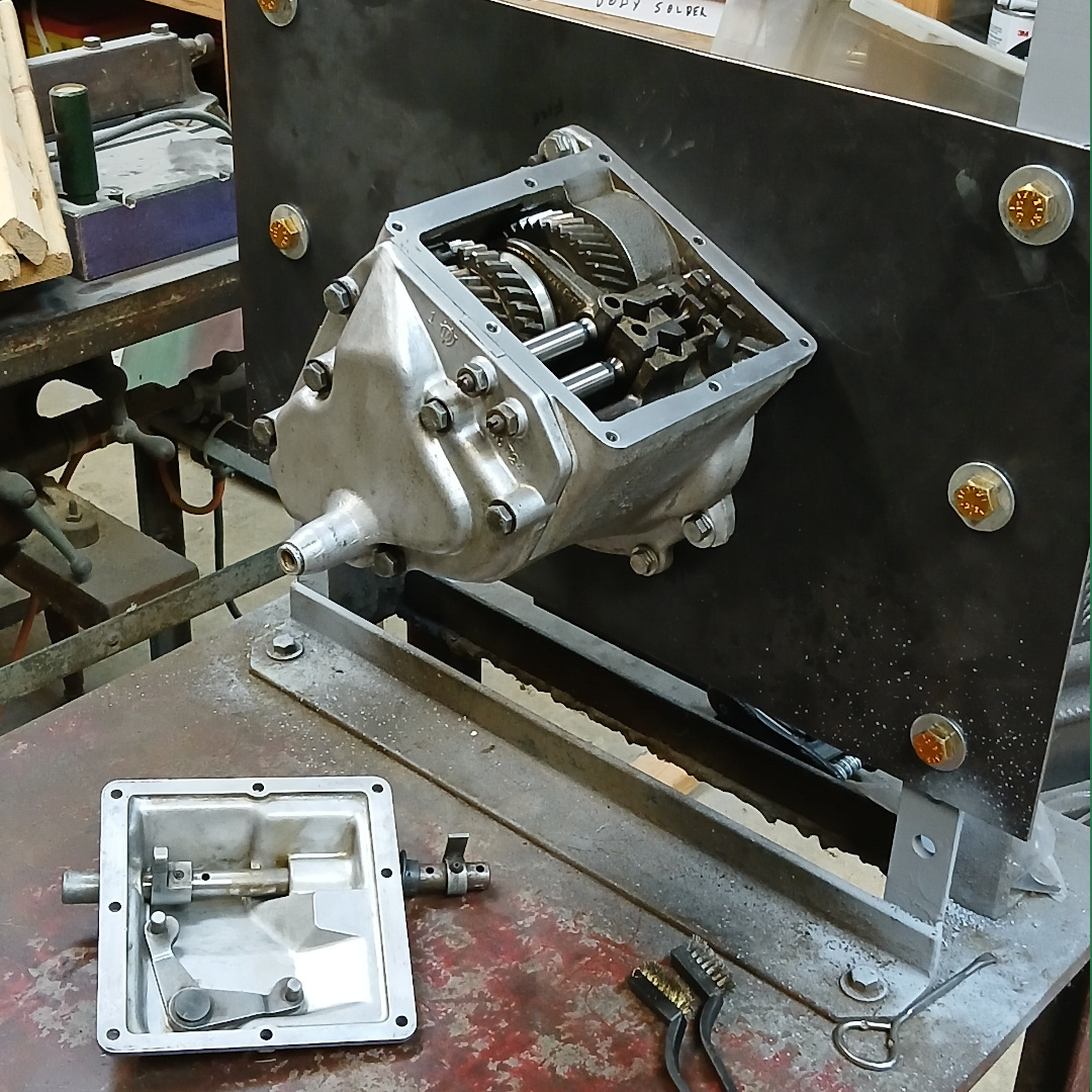
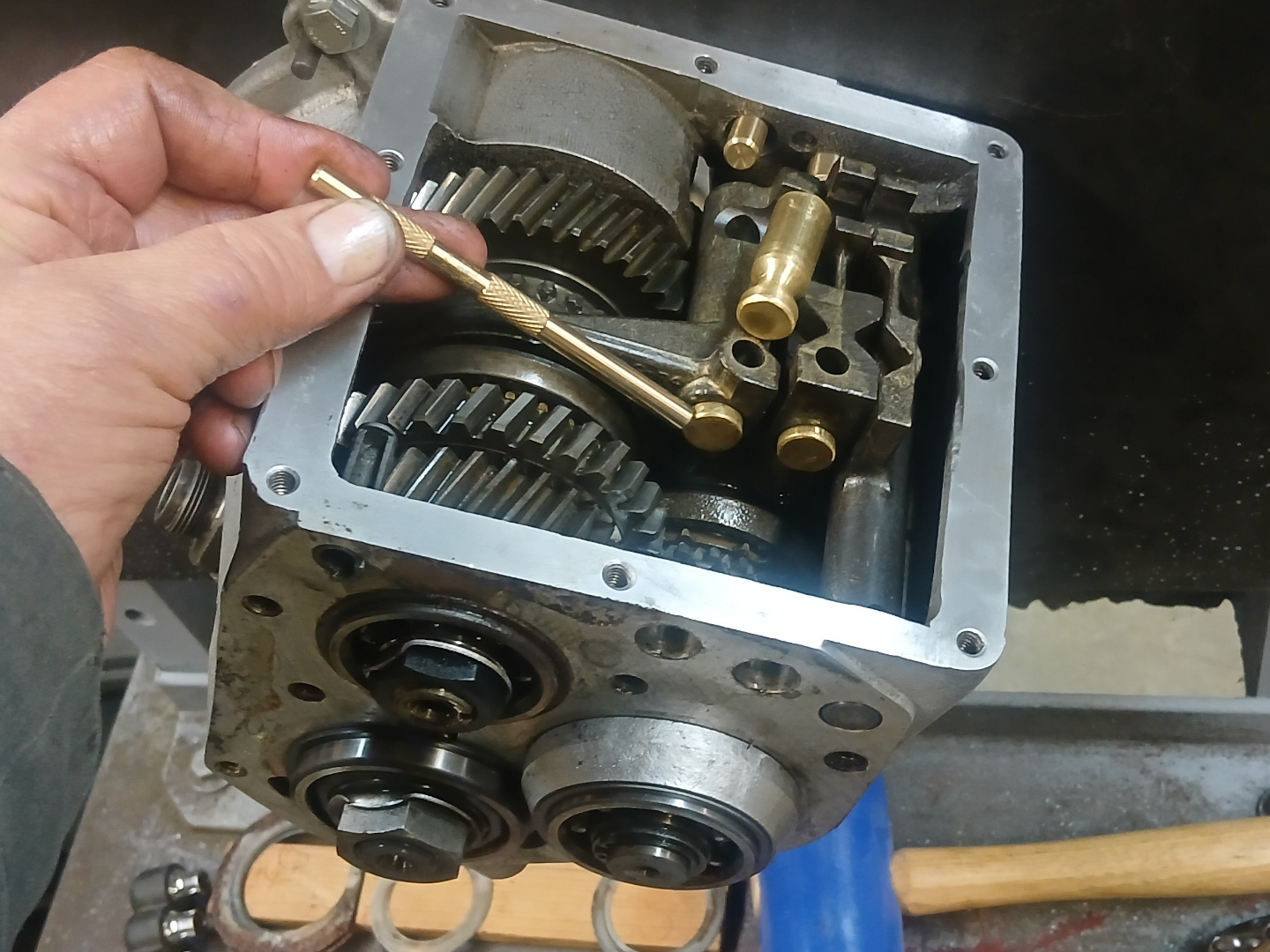
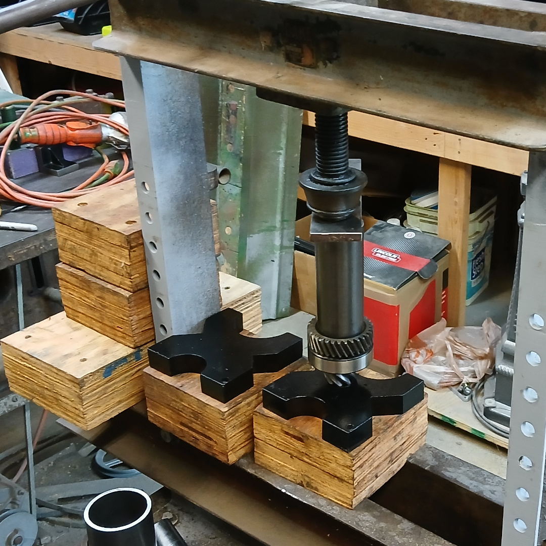
I am no where near ready for installation of the transmission but just had to know if I had a good one or not. I was hoping that I might only have to deal with the infamous loose pinion shaft nut and call it a day. But, alas, it wasn’t nearly that simple, and a complete disassembly was required. After thinking ahead a little, and watching a few Youtube videos, I decided to buy some 14 mm brass rod and make some shift bar poppet ball retainers (SAAB special tool 784069). Not having a lathe, I cobbled up a motor and bearing assembly and then used a flap disk to grind detents into the shaft. Figure 1 shows the setup, and Figure 2 shows the end result. These worked very well and were very useful. The left over 14 mm bar turned out to be useful as well.


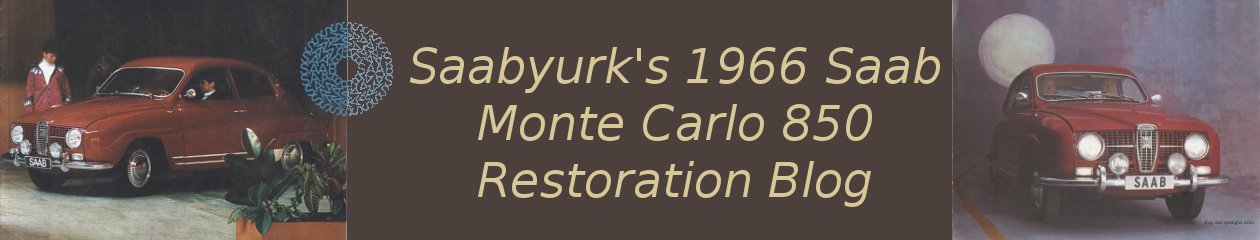
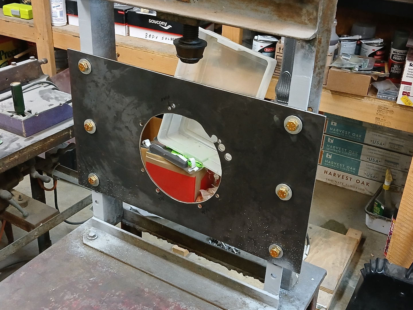
I don’t have a transmission jig, so I made a mounting plate with 3/16″ (4.8 mm) thick steel, and then mounted the plate to my screw press. See Figure 3. This worked well but I later decided mounting it to the press was not the best idea, and I made wood supports for it out of lumber and plywood. Figure 4 shows the tranny mounted for disassembly.
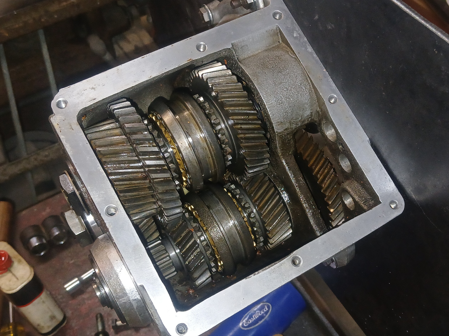
Upon removing the rear cover, I found the large shim rings had rusted badly. Seems strange because there was no water in the oil, and there were no other internal signs of rust. Note, as seen in Figure 5, the two gear shift rails were left attached to the cover as per the shop manual instructions. Thus, no adjustments were disturbed.

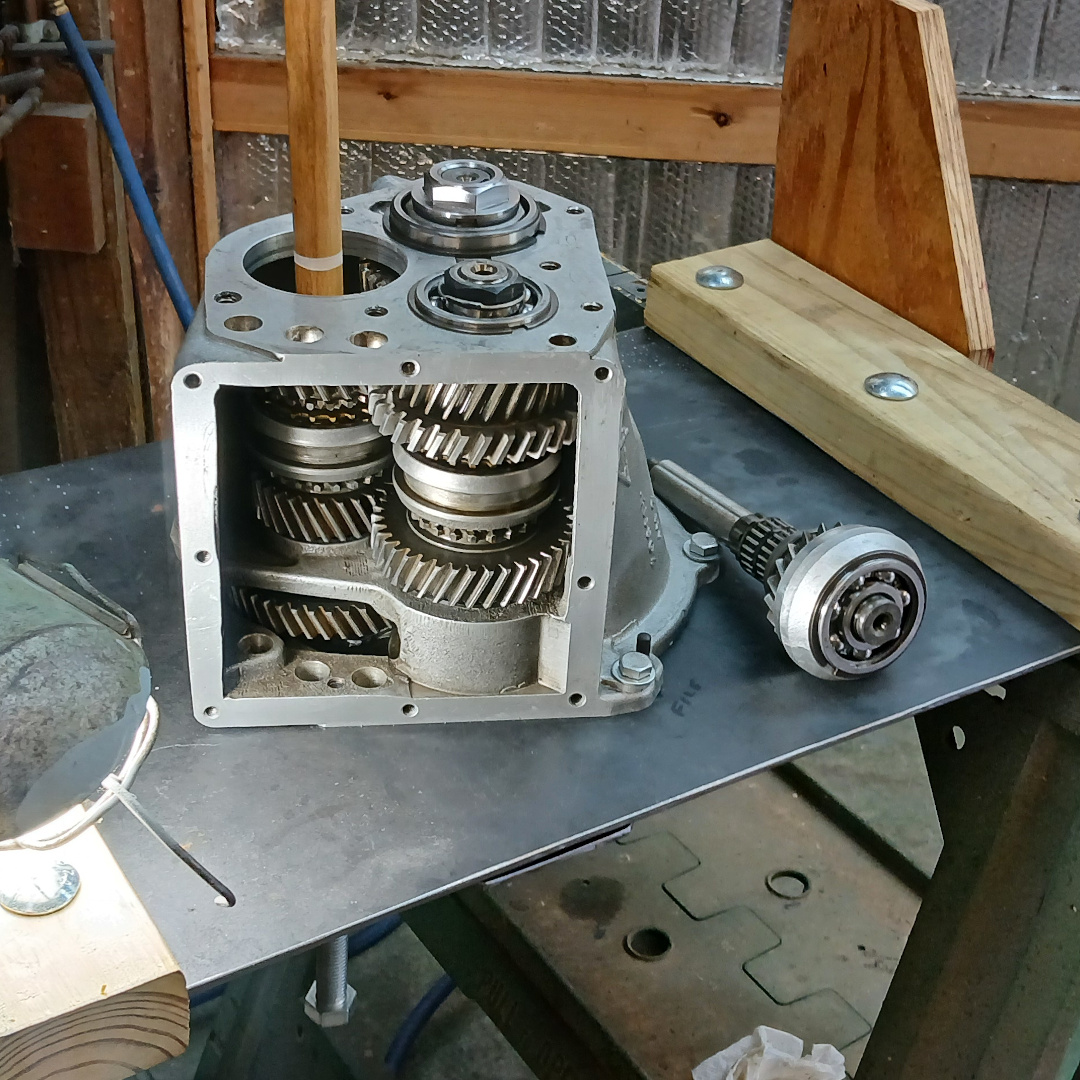
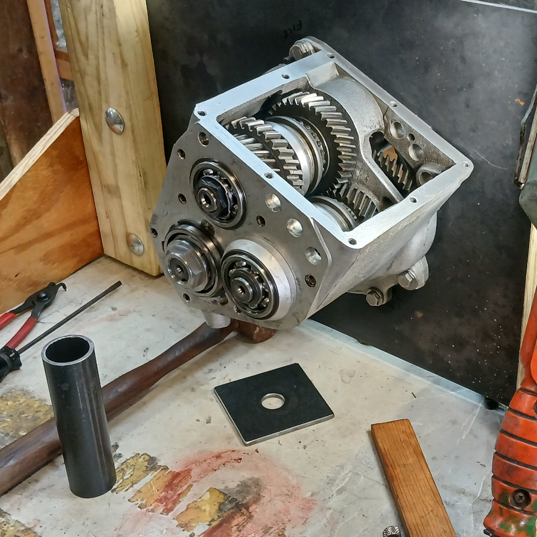
To remove the two forward gear shift rails, because they were still attached to the rear cover, I tapped each one rearward a little at a time, using the 14 mm brass rod as a drift. When driven just far enough to allow room for insertion of the poppet ball retainers, I inserted those, and then I drove those rearward a little at a time until I felt the poppet balls enter the detents on the retainers. I then pulled the rear cover with rails the rest of the way. See Figure 6. The procedure for the reverse rail was similar except that I had to drive it forward just enough to knock the front seal out of the case. Then I drove it out reward, leaving the rest of the transmission accessible as shown in Figure 7.
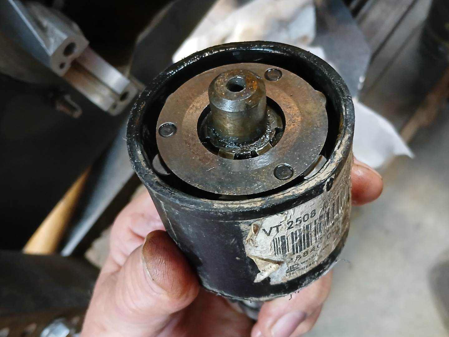
Next up was the freewheel device. I cut the end off an old Shopvac tube that happened to be the right diameter. I used it to keep the rollers and springs contained as shown in Figures 8 and 9. I inserted a spare input shaft into the freewheel device to pull it out. Then I released the rollers and springs into a ziploc bag as shown in Figure 10.


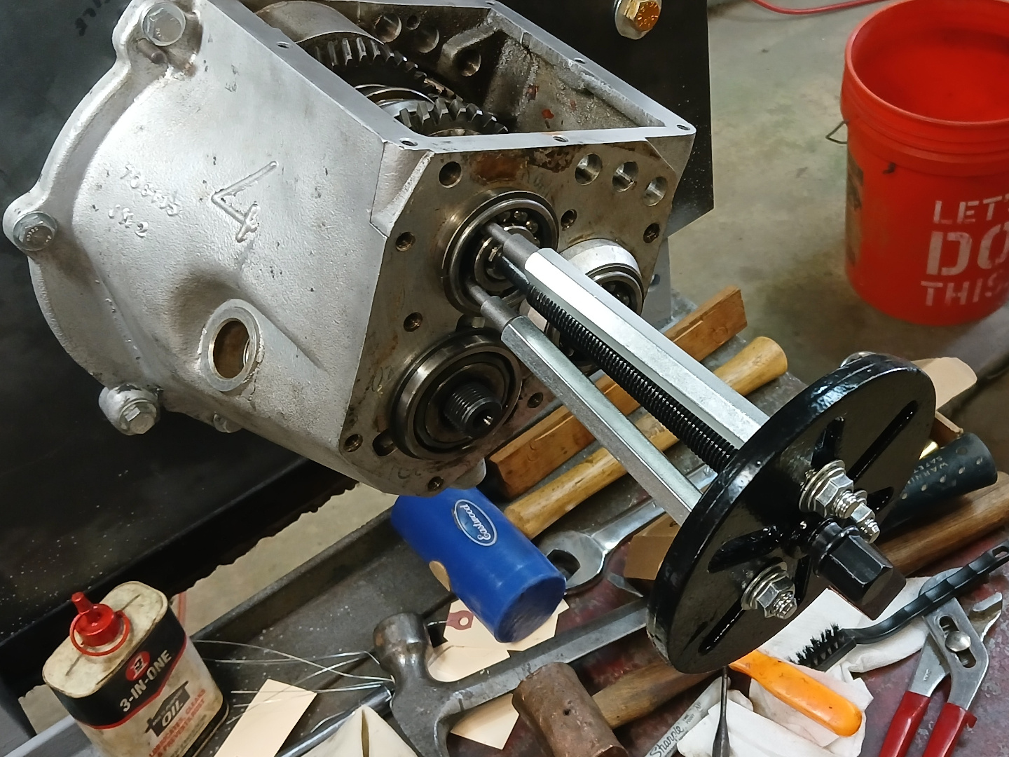
Not having the SAAB transmission jig, I cobbled up a 3-screw press which mounts in place of the differential. I didn’t need this just yet, but it came in handy when removing the transmission shafts later on.

I pulled the main shaft rear bearing in the next step as shown in Figure 12. Please note that this type of puller requires destruction of the bearing cage, so a new bearing is always required.
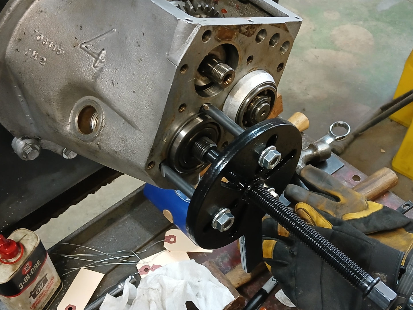
The rear pinion shaft bearing was a bit more difficult to pull. SAAB didn’t provide much room for a puller in the three small cavities around the bearing. I was able to use the same tool for this bearing, but I had to buy three metric bolts and grind the heads into the shape of a hook that would fit into each cavity. This worked well, and Figure 13 shows the bearing being pulled.
Pressing the intermediate shaft was the next small problem. I didn’t have the SAAB special arbor tool 784110, and I consequently made a substitute from an old tie rod end separator as shown in Figures 14 and 15. It worked but was a bit cumbersome when I had to add spacers on the driving end. But it got the job done by using one of the three screws on my press shown above.

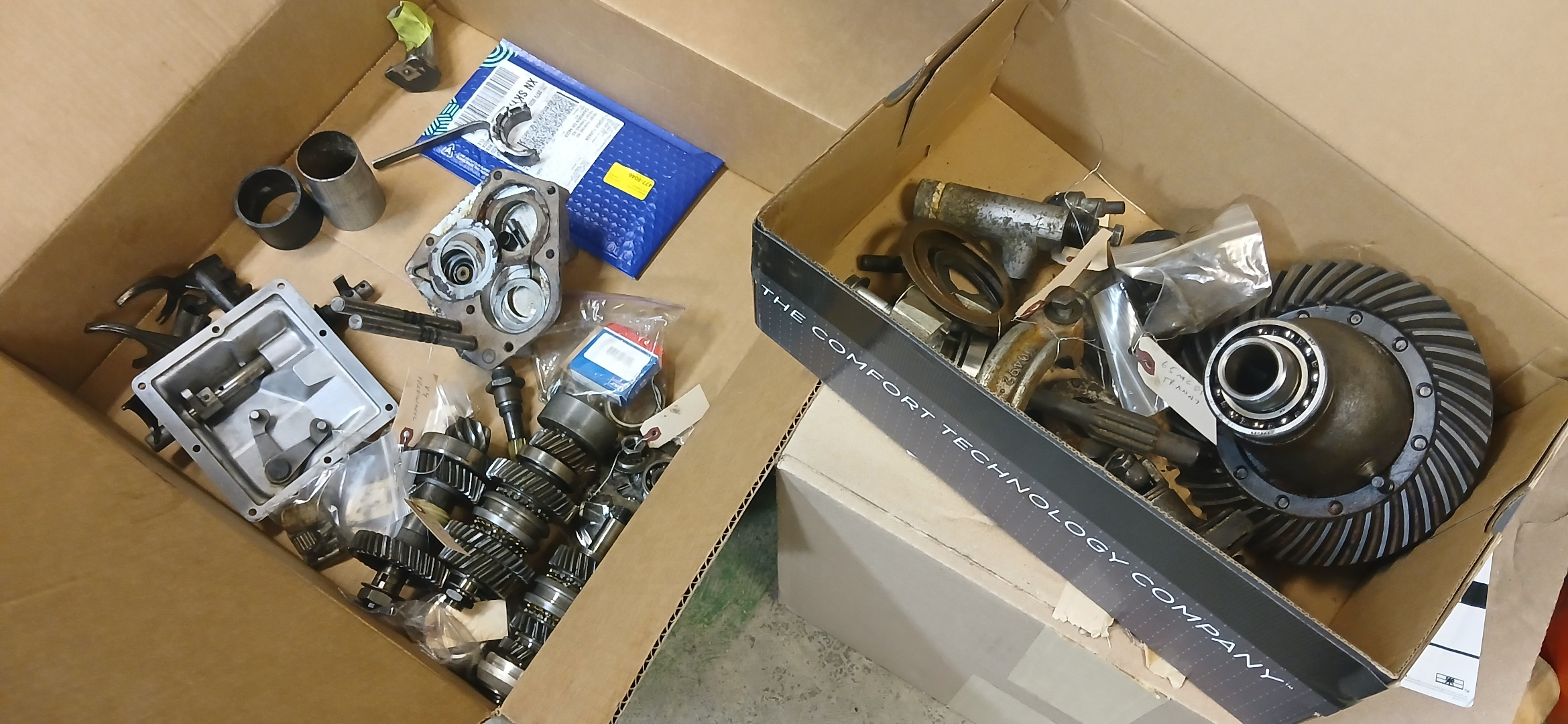
One more special tool that I made, but which wasn’t really necessary, is an intermediate shaft supporting tool number 784125. It is shown in place in Figure 16. Figure 17 shows the intermediate shaft, reassembled, after removal. Figure 18 shows the now empty case ready for cleaning, and Figure 19 shows two boxes of parts ready for examination, replacement and re-installation.


Reassembly
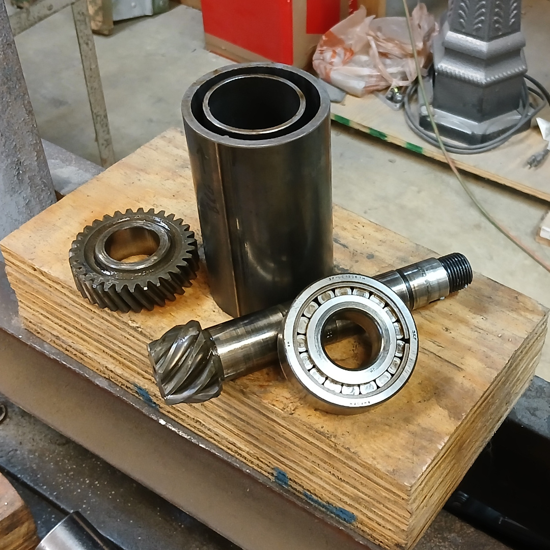
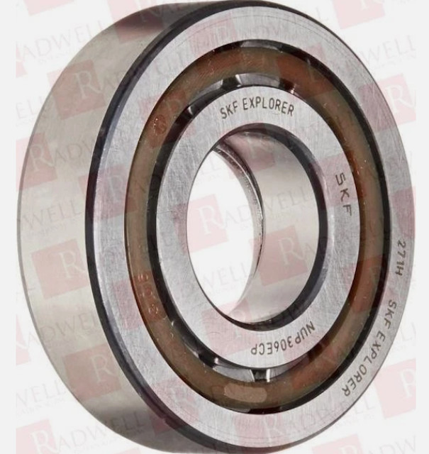
First up, is a new front pinion bearing. I was able to press off 4th gear and the front pinion bearing with the cylindrical arbors shown in Figure 20. The bearing appeared to be okay but I decided to replace it anyway. Apparently, the original is no longer made, so I went with an SKF NUP306ECP (similar to the stock photo in Figure 21) as used by some other re-builders.
Next up is the differential which had a rusty ring gear, fully disassembled in Figure 22. The new ring gear from Saabklubben was pressed on as shown in Figures 23-24, and the completed differential is shown in Figure 25 with two new bearings installed.
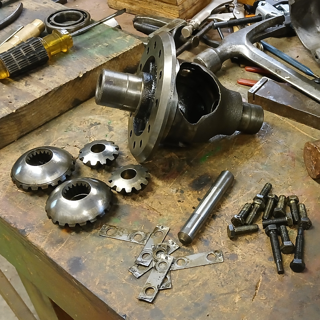

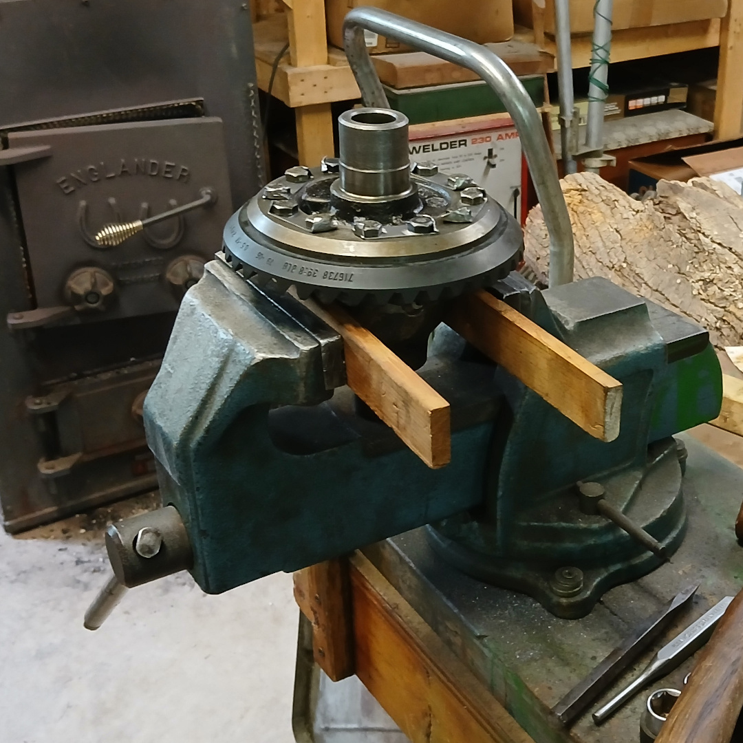

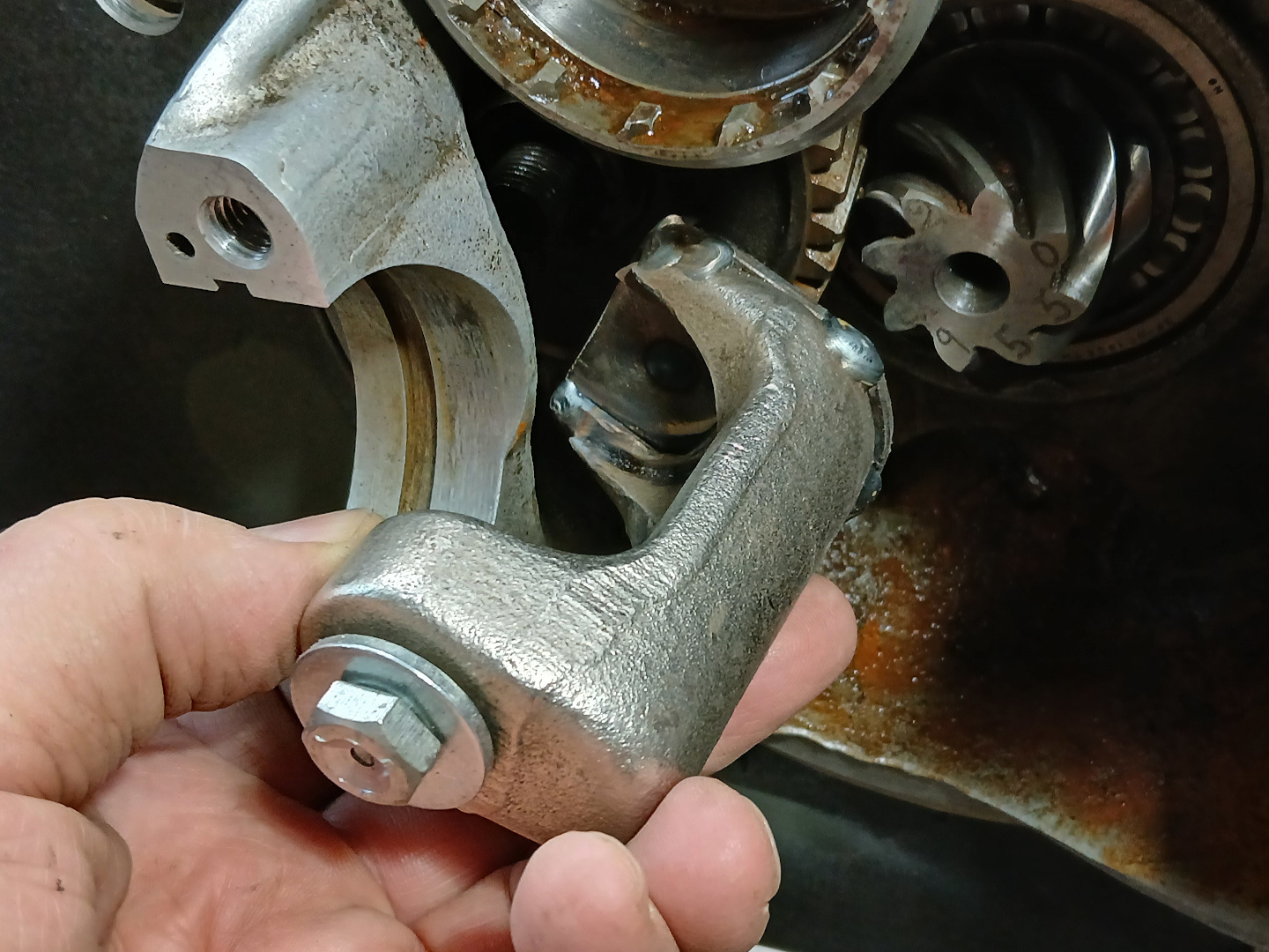
Figure 26 shows the numbers etched on the tip of the pinion gear. You will notice that”2491″ matches the number in the ring gear, as is required. The “+11” is a measurement adjustment, more fully described in the shop manuals. See also Figure 33.
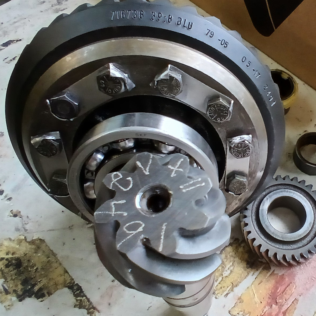
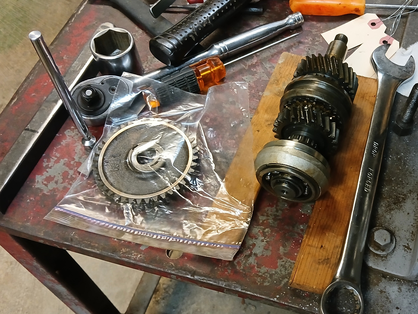
Figure 27 shows 4th gear and the new pinion front bearing being pressed onto the pinion shaft. Figure 28 is an internal view of the assembled pinion shaft, including the speedometer drive gear.

With the pinion shaft installed, it was possible to install the main shaft above the pinion shaft as illustrated in Figure 29. With the main shaft installed, it was then possible to assemble the intermediate shaft. For this, it was very convenient to tip the transmission face down. This allowed the gears of the intermediate shaft to be stacked upon each other, with a dowel rod ensuring they didn’t fall over as shown in Figure 30. Removal of the dowel rod allowed for insertion of the intermediate shaft from the bottom side. The completed assembly is shown in Figure 31.
The front gear of the intermediate shaft was then a bit tricky to install, but doable. Figure 32 shows the setup for torquing the shaft end nut. Because of the crow’s foot extension, a little attention has to be paid to the effective length of the torque arm, with an appropriate adjustment to the desired torque value.


With everything torqued to spec, it was time to measure the depth of the pinion shaft. I didn’t take enough photos, however, the tools and setup for measuring the distance from the tip of the pinion gear to the center axis of the differential bearings is shown in Figure 33.
A telescoping gage from the set pictured is set to the distance from the gear to the flat plate. The gage is then measured with a micrometer. The distance is supposed to be 60.94 mm plus 0.11 mm as indicated by the “+11″ etched on the pinion gear. Thus, the distance I wanted was 61.05 plus or minus 0.05 mm. The exact distance is very difficult to measure consistently, however, I was always within the allowed 0.05 mm variance. I had to pull the rear pinion shaft bearing to install one shim to achieve this result on the second try. Figure 34 shows the setup for measuring ring gear backlash. This is adjusted by shimming the differential bearings left or right as described in the shop manual. I hit 0.005” (0.13 mm) on the first try. And finally, the speedometer driven gear is shown in Figure 35. I had to add a brass shim because of excessive end play. You can see the little bit of brass next to the plastic gear.


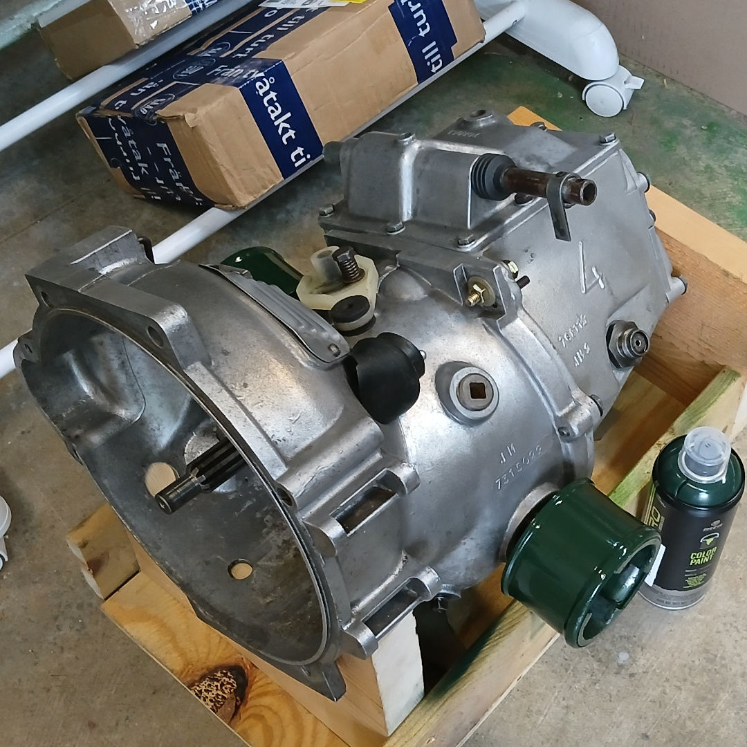
The cleaned up bell housing is shown in Figure 36, and the final transmission assembly (with new rubber parts) is shown in Figure 37.

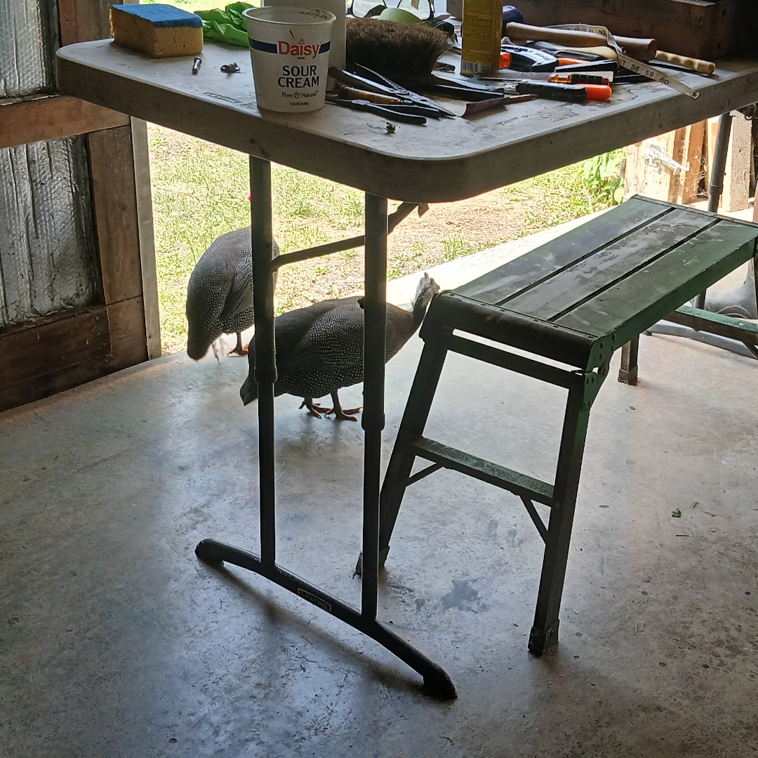
A few guineas would stop in from time to time offering some moral support as shown in Figure 38. Actually, they were looking for a meal worm handout but it was usually a welcome break. Figure 39 is the collection of tools and stuff that I cobbled up to do this job.

In summary, the following is a list as best as I can remember of replaced components: Two differential bearings (new); two intermediate shaft bearings (new); one rear main shaft bearing (new); two pinion shaft bearings (new); one 3rd gear key (used), two pinion shaft shims (new); the pinion shaft (new from Saabklubben); front pinion gear key (used); ring and pinion gear set (new from Saabklubben $$$); new rubber bellows for shifter; new style pinion shaft nut and lock ring (new from Saabklubben); and a new rear gasket.
Absolutely wonderful! You are ingenious and meticulous!
Cheers!