
It has been too long, and I am running out of time age-wise, but I am feeling optimistic now that I have the MC850 on wheels. Unfortunately, my progress has been chaotic and disorganized, working on what appeals to me at the moment. This post is another example of that.
Getting started with the wiring harness, fuse box and relays
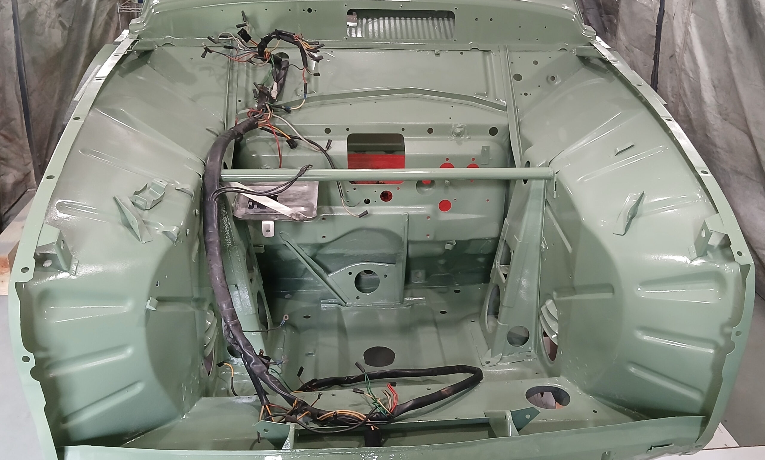
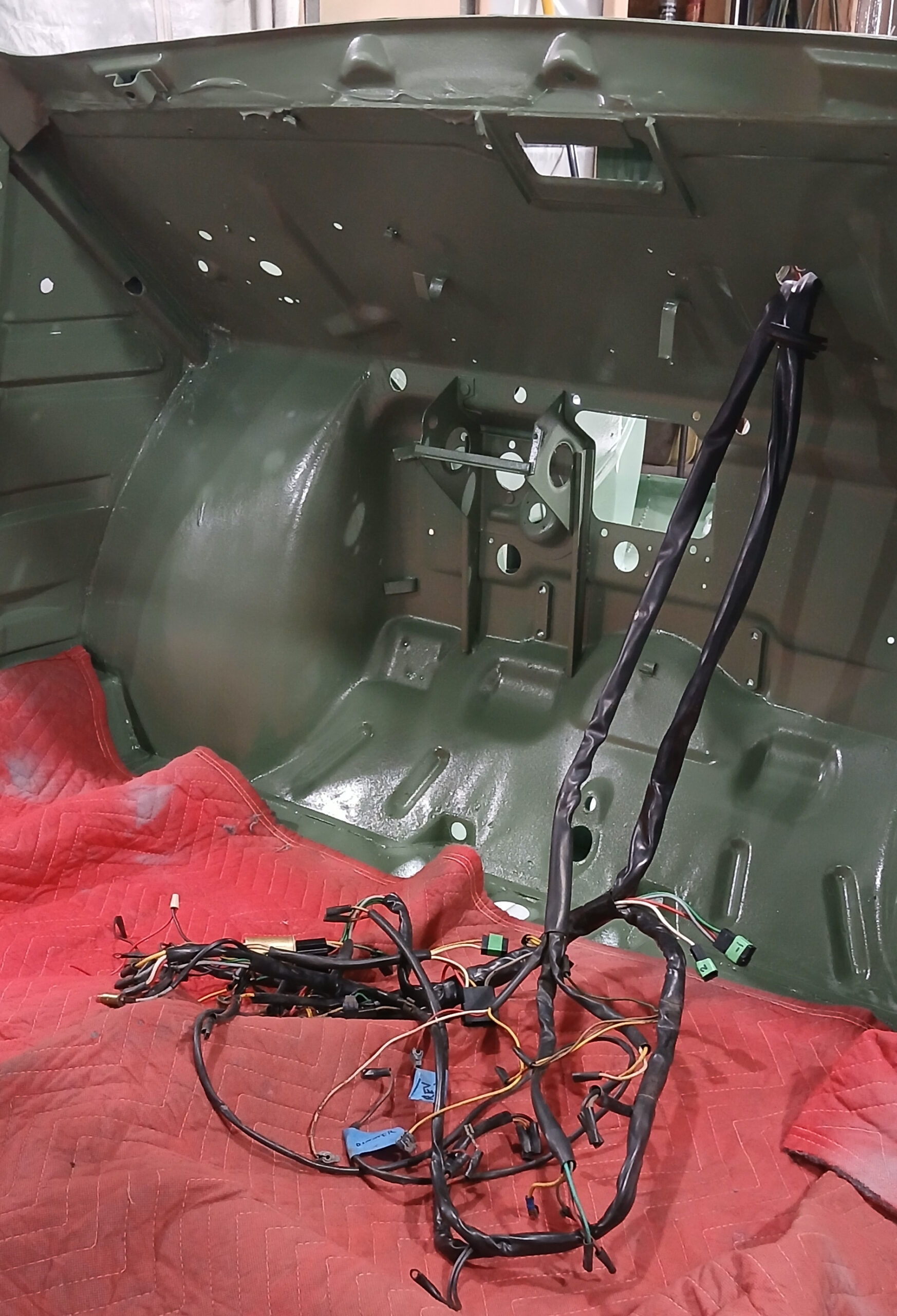
When I pulled the wiring harness many years ago, I thought I would easily remember how it went back in. It’s a good thing I have an unmolested 96 of the same year or I’d still be scratching my head. Figures 1 and 2 show that I finally figured out which sections go inside the car, and which sections go to the engine compartment as shown below.
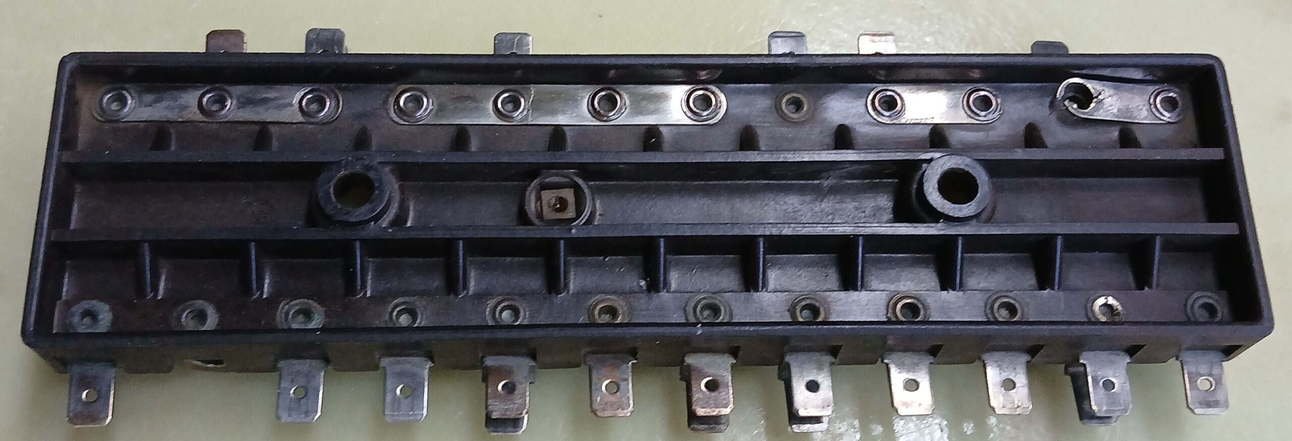
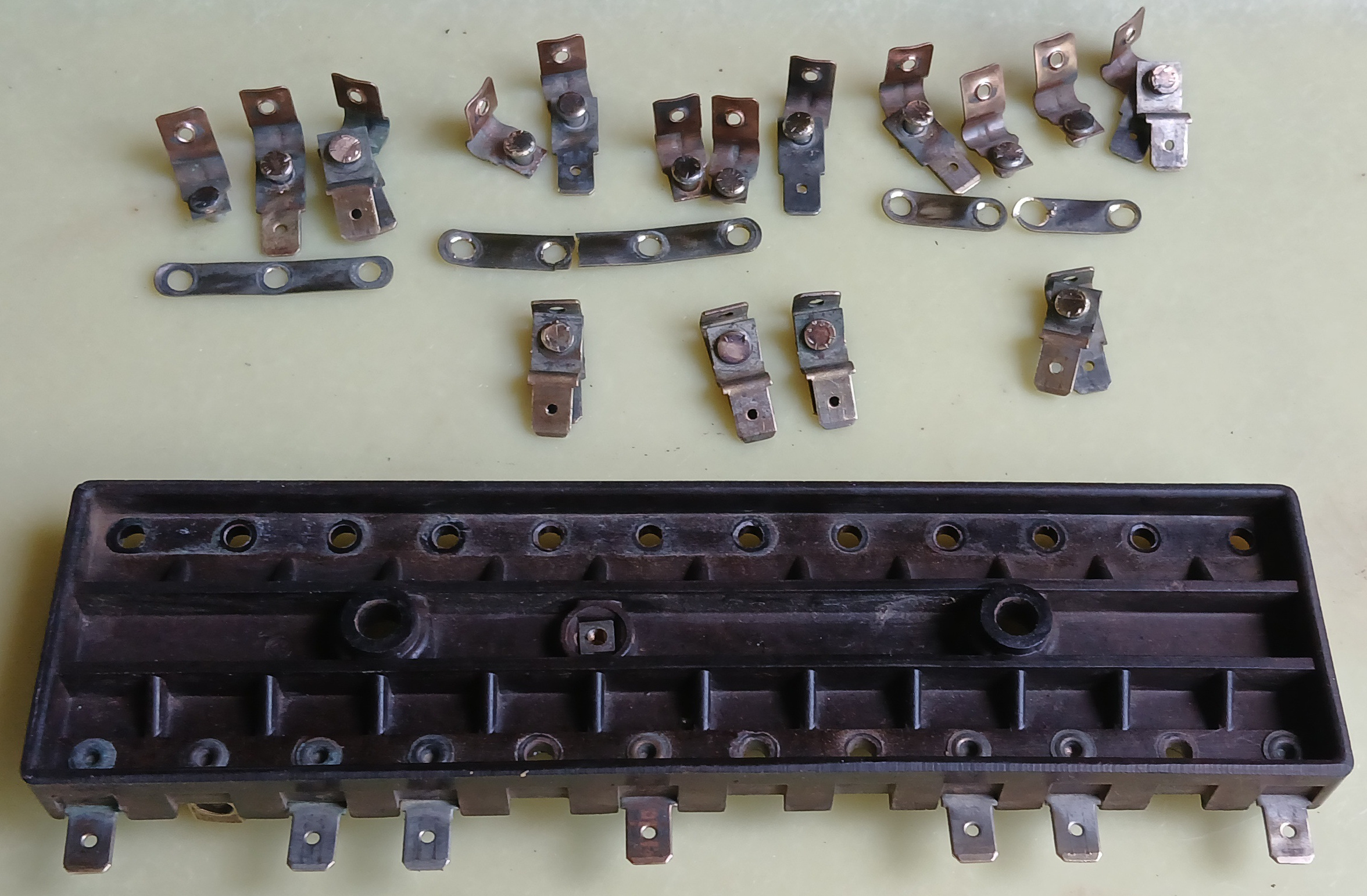
Having the wiring harness somewhat routed, it was time to install a fuse box. Unfortunately, the original MC850 fuse box had been replaced sometime with a later V4 style fuse box. The internal bus arrangement was different and some external wiring hacks had been made to make it work. I found that I had a 1966 style box to replace it. Unfortunately again, it exhibited very high resistance across riveted connections, and one bus bar was mysteriously fractured. Apparently, riveting connectors on bakelite is not a good idea because the bakelite shrinks slightly over time, allowing corrosion to interfere. Figure 3 shows the bus structure of the correct 1966 fuse box, and Figure 4 show the fuse box with all riveted connections removed. The remaining rivets were not electrical connections, just place holders.
I decided the best repair method for me was to replace the rivets and bus bars with brass nuts, screws and brass plate. It doesn’t look original but it’s out of sight and works quite well. See Figures 5 and 6.
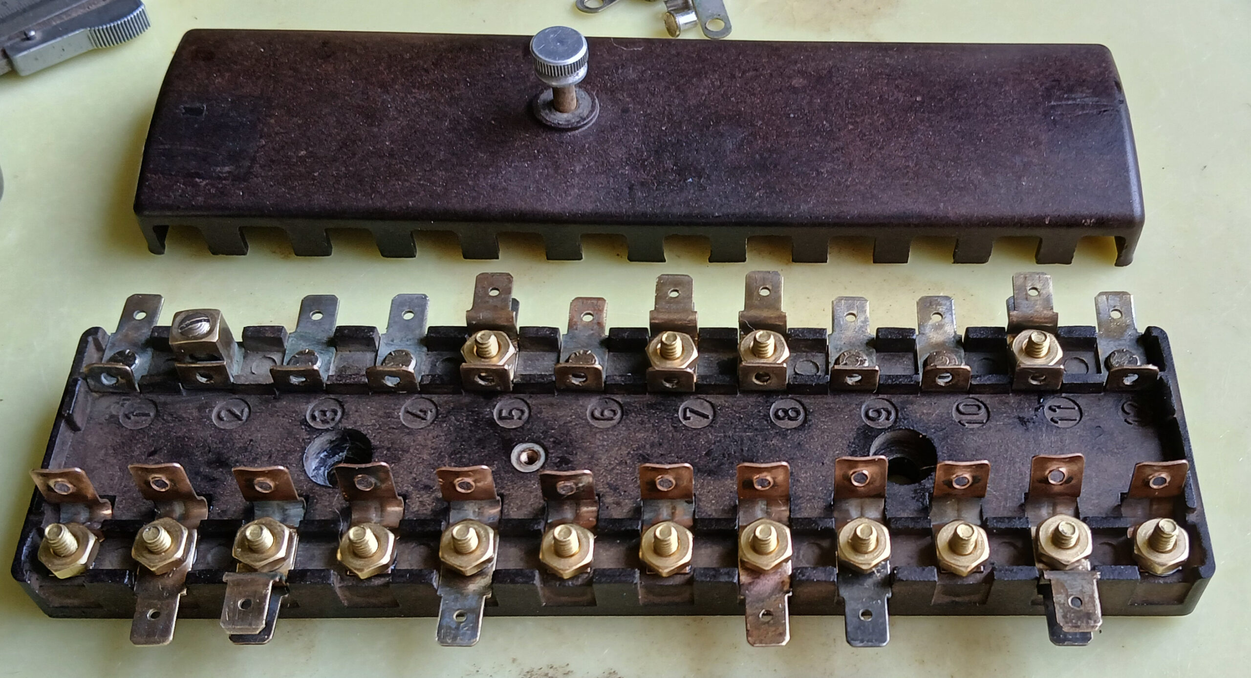
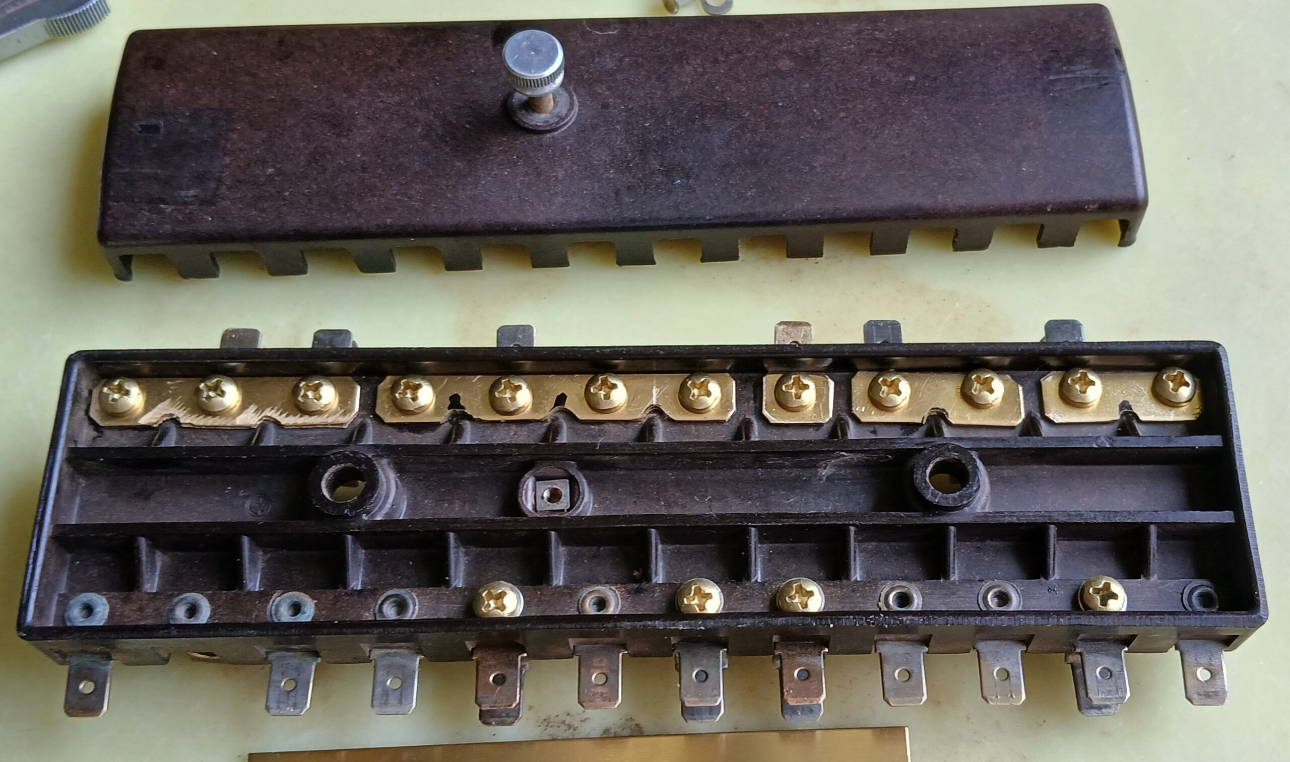
Figure 7 shows the installed fuse box. Figure 8 shows the interior cable routed. Before routing it, however, I decided I should lay down the sound deadening material first. Installing the sound deadening material later would have been difficult.
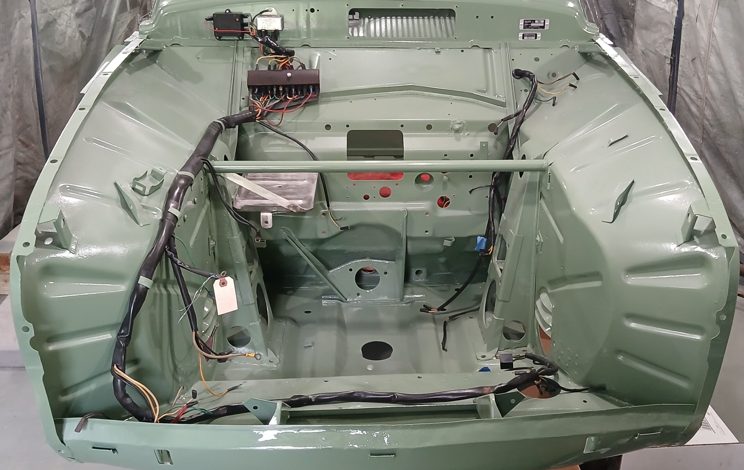
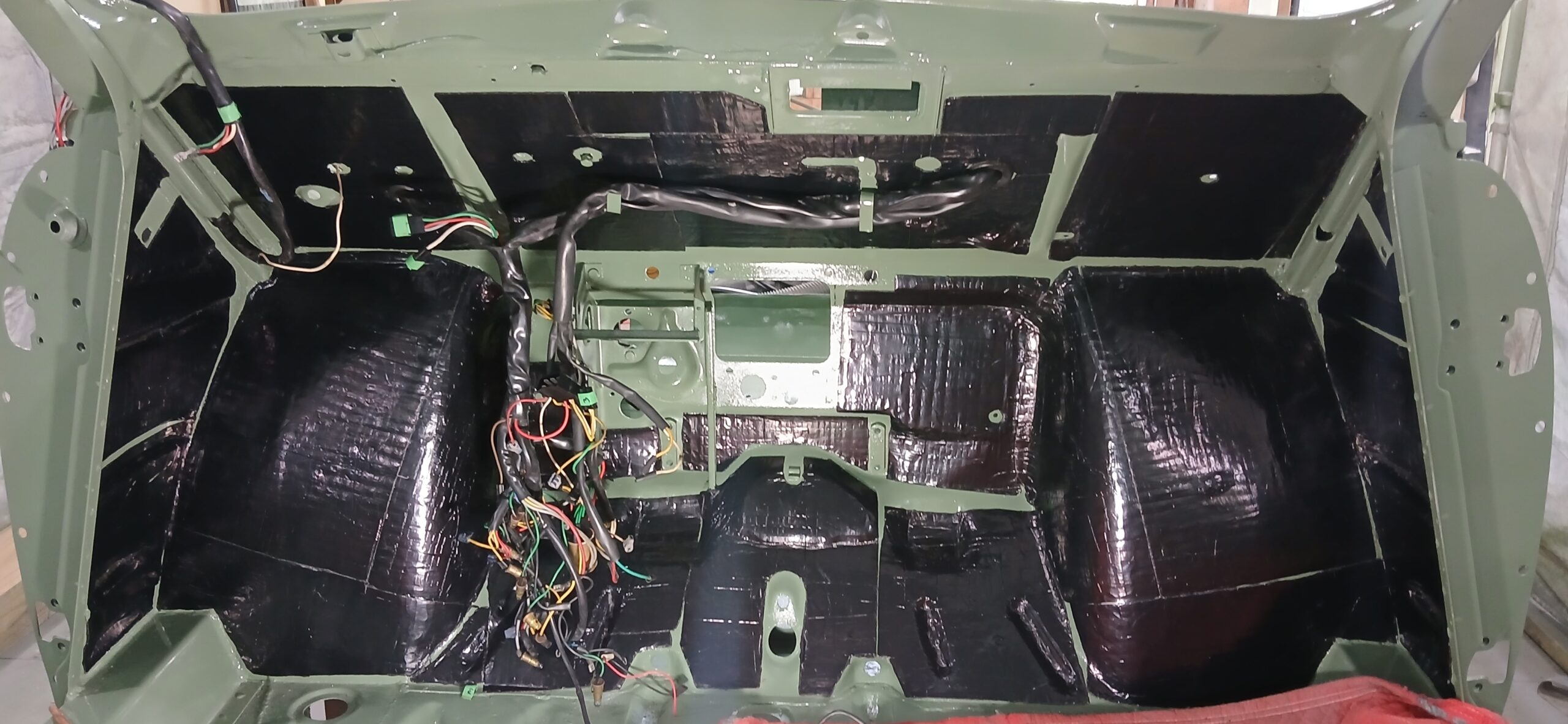
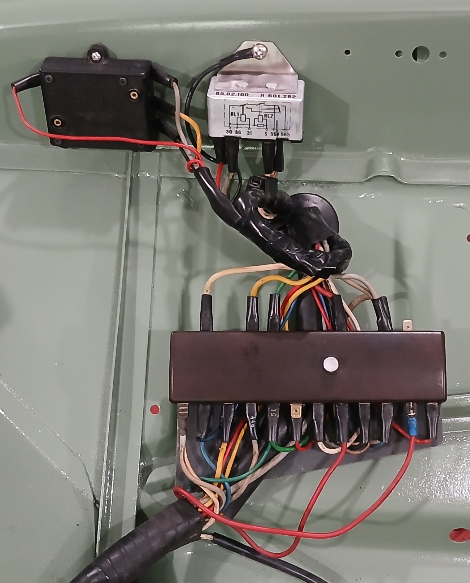
Figure 9 shows the fuse box installed below the oil pressure monitor and the headlight relay box. The oil pressure monitor contains the Arduino circuit discussed in the previous post, and the headlight relay box is from an early C900 which allows me to use the steering column mounted headlight dimmer/flasher.
Some Parts Cleaning and Painting
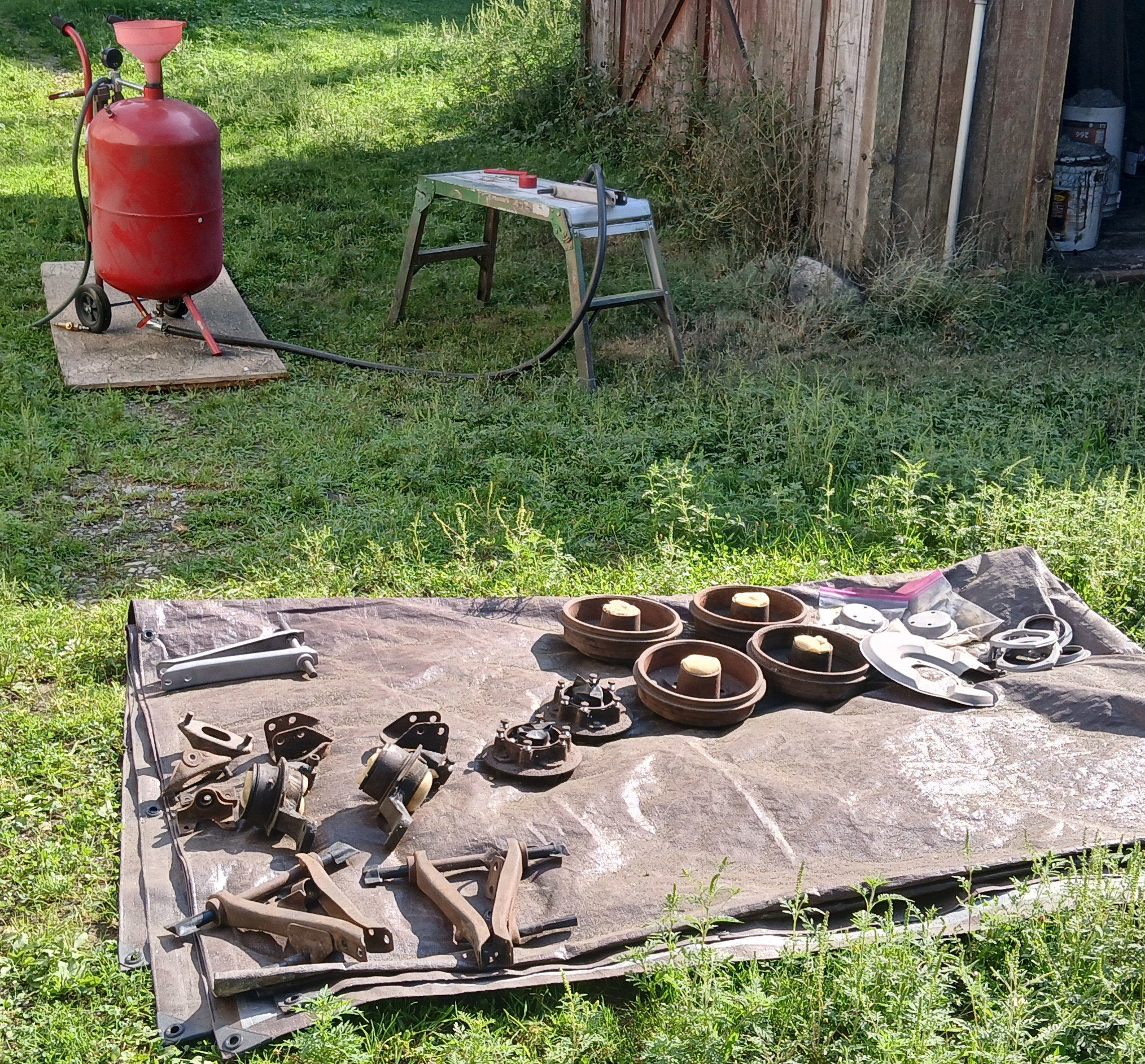
Having lost interest in further wiring, I turned my attention to the suspension, with the hope of getting the MC850 onto wheels on the ground. The summer season was ending, and I needed to get any media blasting and painting done before cold weather. Figures 10 and 11 show some of the media blasting process using the finest grade of coal slag media.
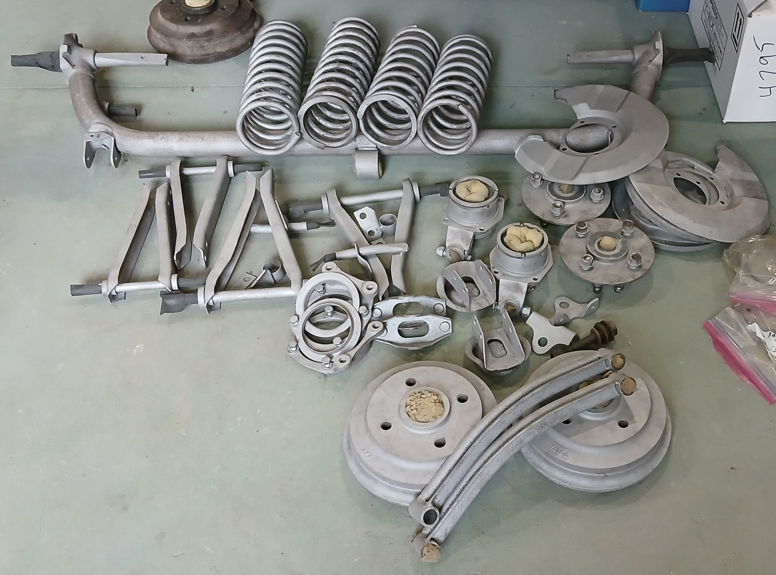
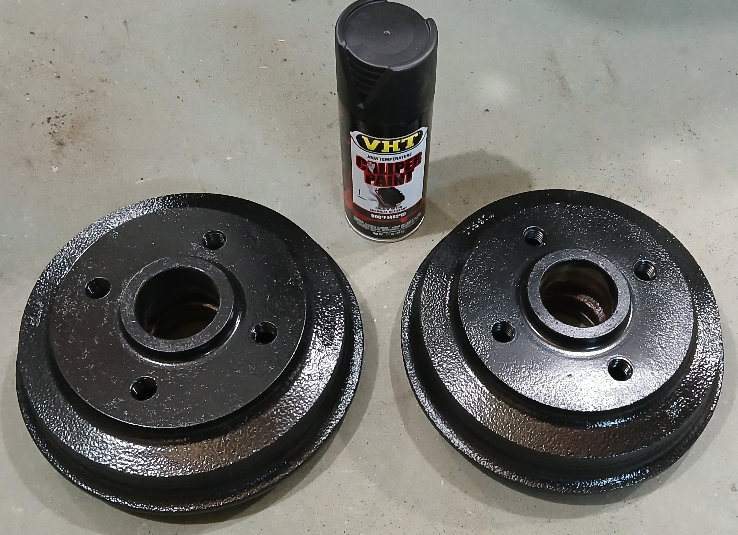
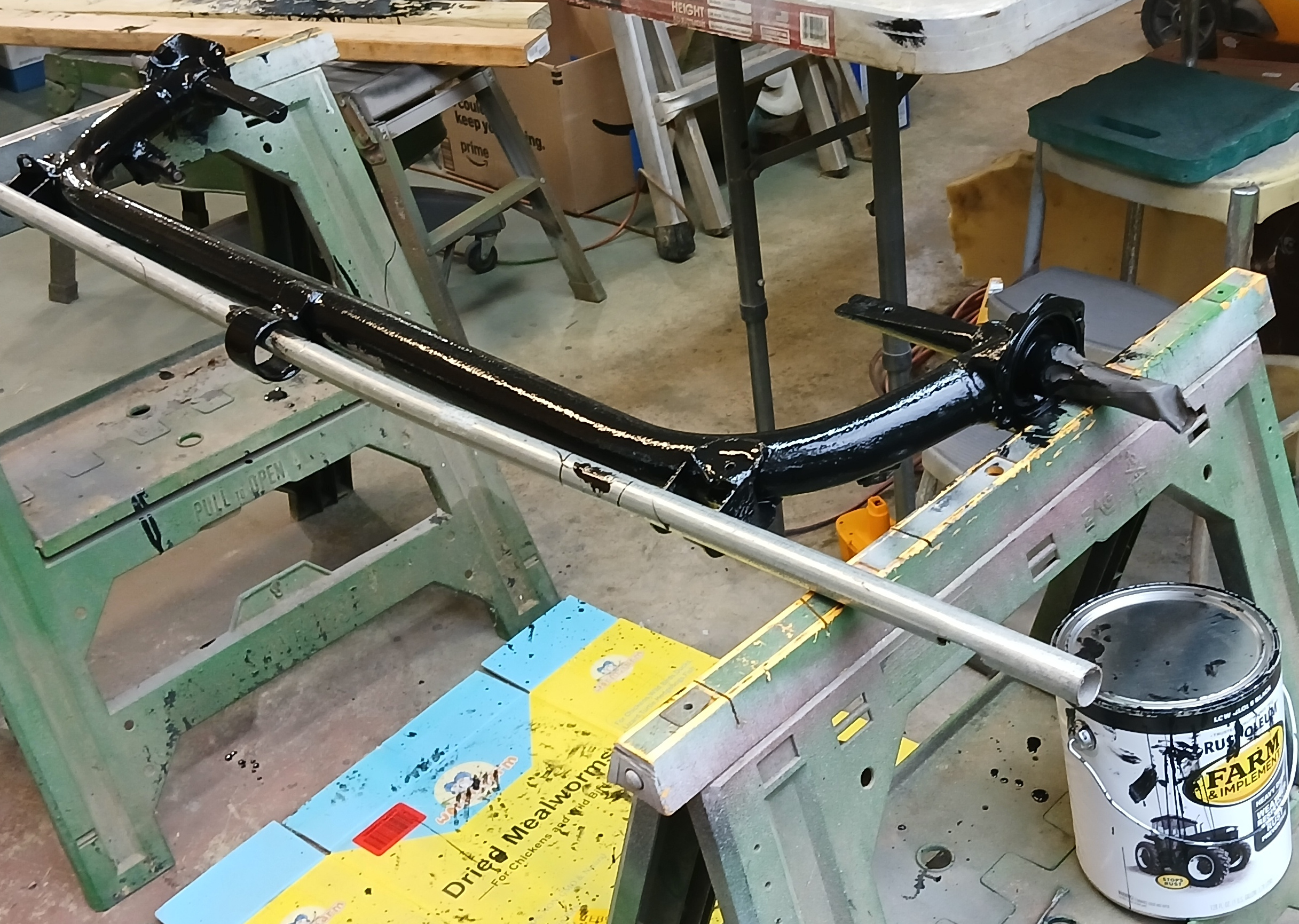
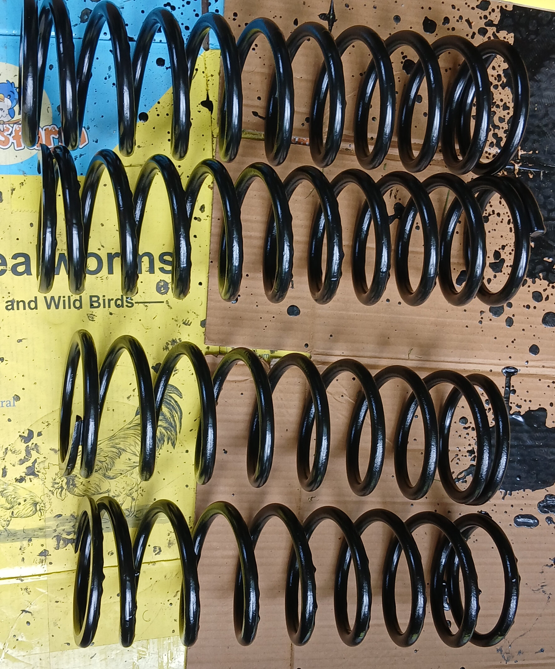
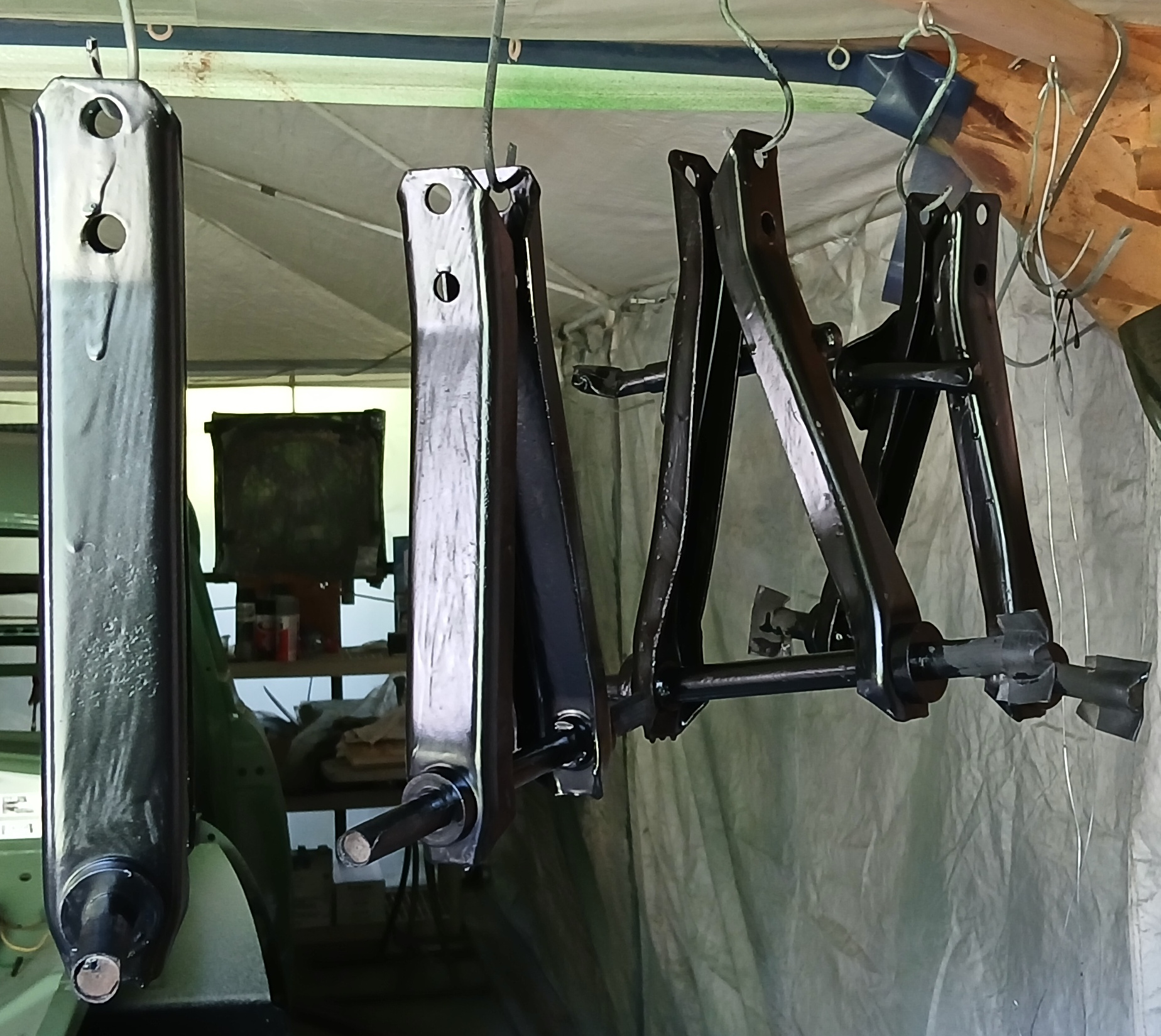
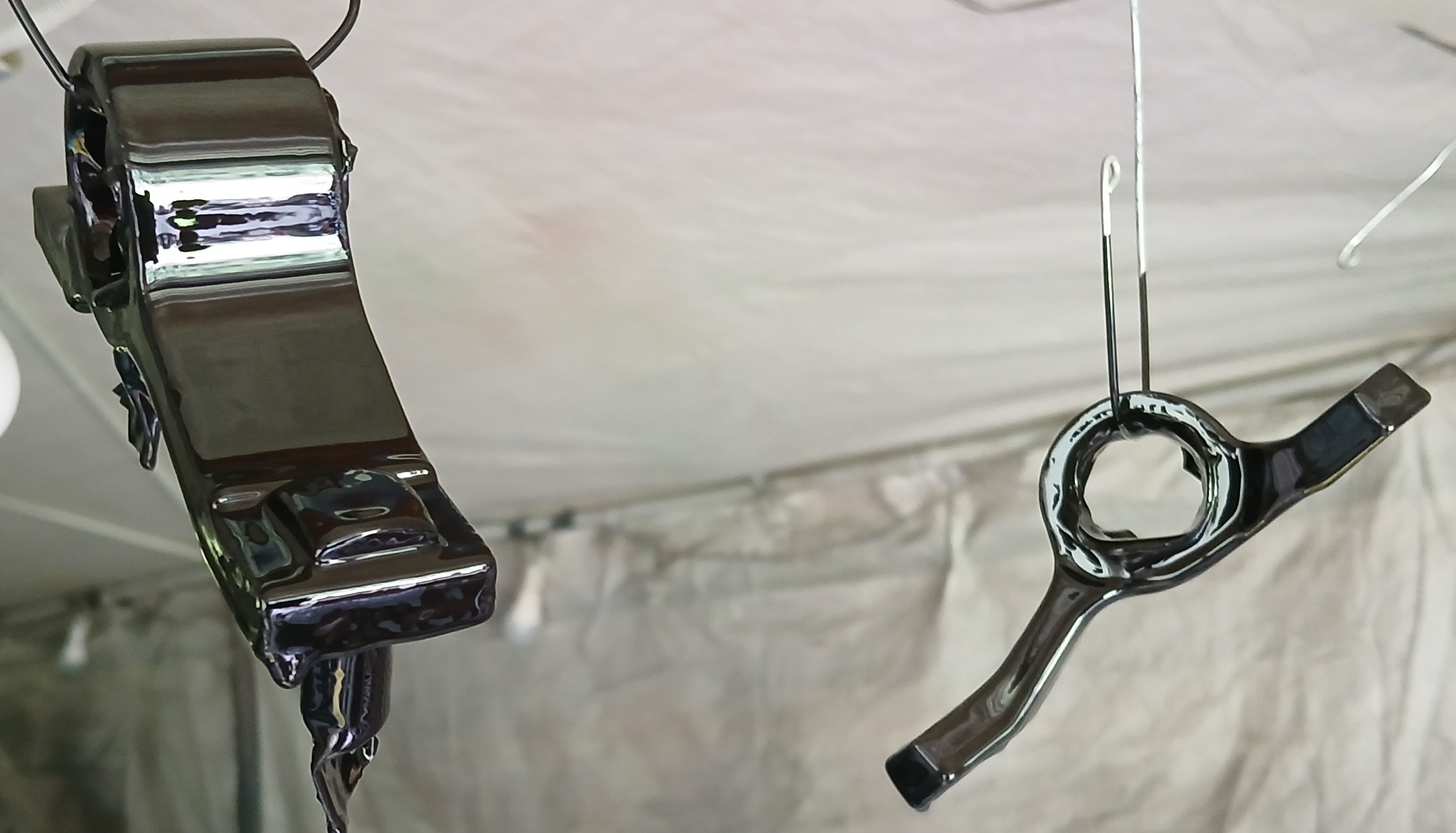
Figures 12-16 show the results of some of the painting. The brake drums got 3 coats of VHT caliper paint while everything else got a thick coat of Rust-Oleum Farm and Implement paint. I painted the smaller parts by simply dipping them into the gallon bucket. I painted the coil springs by pouring some Rust-Oleum into a tray and rolling the springs in the tray. I just hung them on hooks to let the excess run off. I worked pretty well, and the farm and implement paint seems pretty tough.
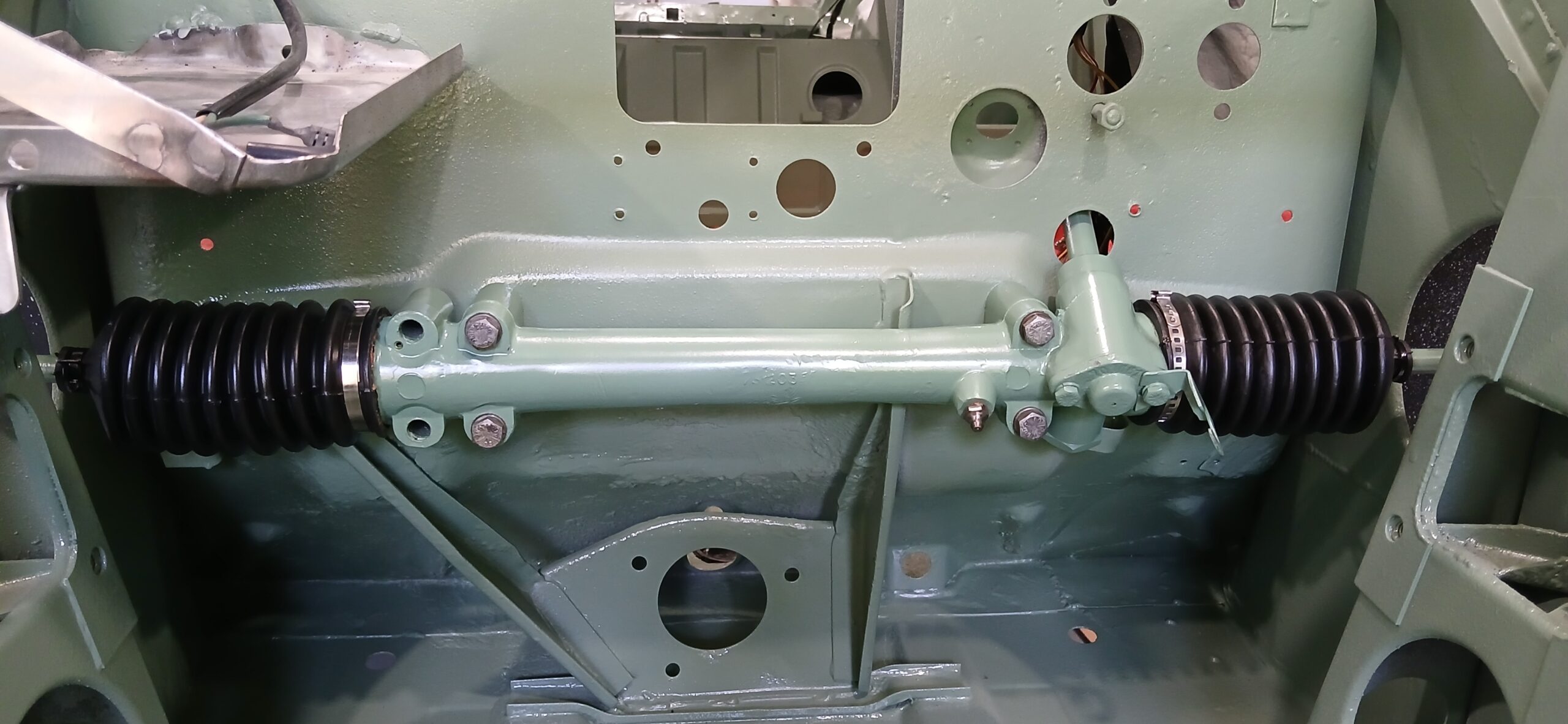
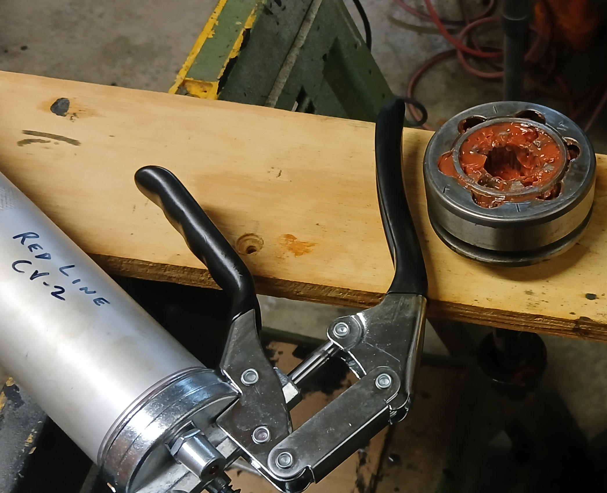
While the paint was curing for at least seven days, I turned my attention to the steering gear. I selected the best from my collection for use in the MC850. Figure 17 shows the rather dirty gear (and this was after some cleaning). I removed all old grease (or at least all that I could get to), and I lubricated the rack and the outer ball joints with Red Line CV-2 red moly grease which seems to be great stuff. Figure 18 shows the finished steering gear. I painted it with Rust-Oleum 2X Moss Green which is very close to the color of the MC850.


Returning to the suspension, Figure 19 shows my rather clumsy method of pressing a new center bushing in the rear axle. This actually worked quite well. However, removal of the old bushing was impossible to do in one piece. I had to drill out the rubber, and gently hack saw the outer sleeve until I could collapse it. In the end, I decided it hadn’t been necessary anyway because the old bushing was still very good. But I like new better. Figure 20 shows the installed bushing.


After pressing new bushings into the front control arm mounts and the rear control arms (a more mundane process using my screw press), I turned my attention to installing the suspension on the MC850 body. I first installed the steering gear as shown in Figure 21 because it was necessary for linking the steering arms of the front suspension.
Installing the Suspension
Working by myself, at age 83, I needed some helping hands to hold the rear axle in approximate position while I bolted the center bushing mount to the body. Some old life vests did the trick as I bolted the rear axle to the body as ahown in Figures 22 and 23.
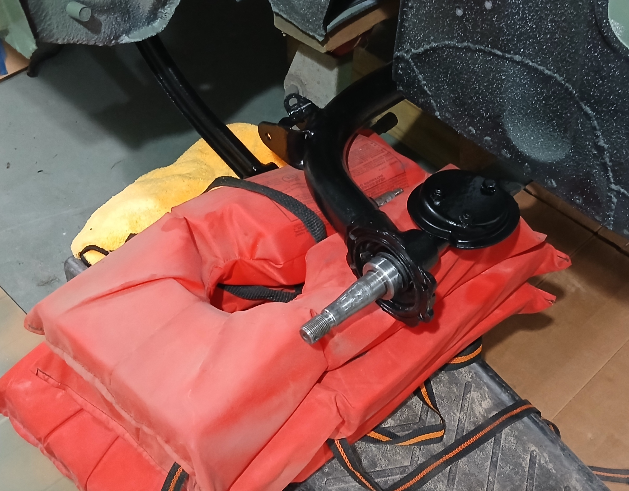
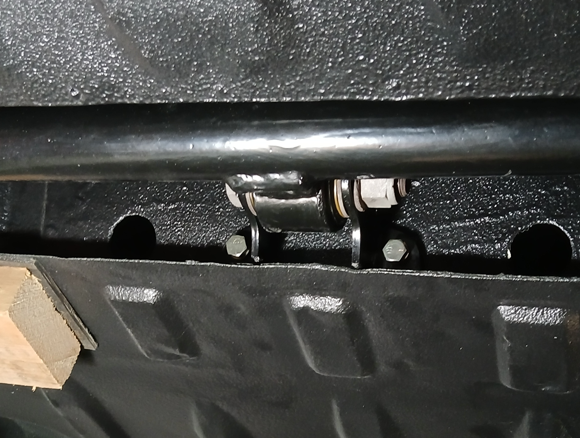
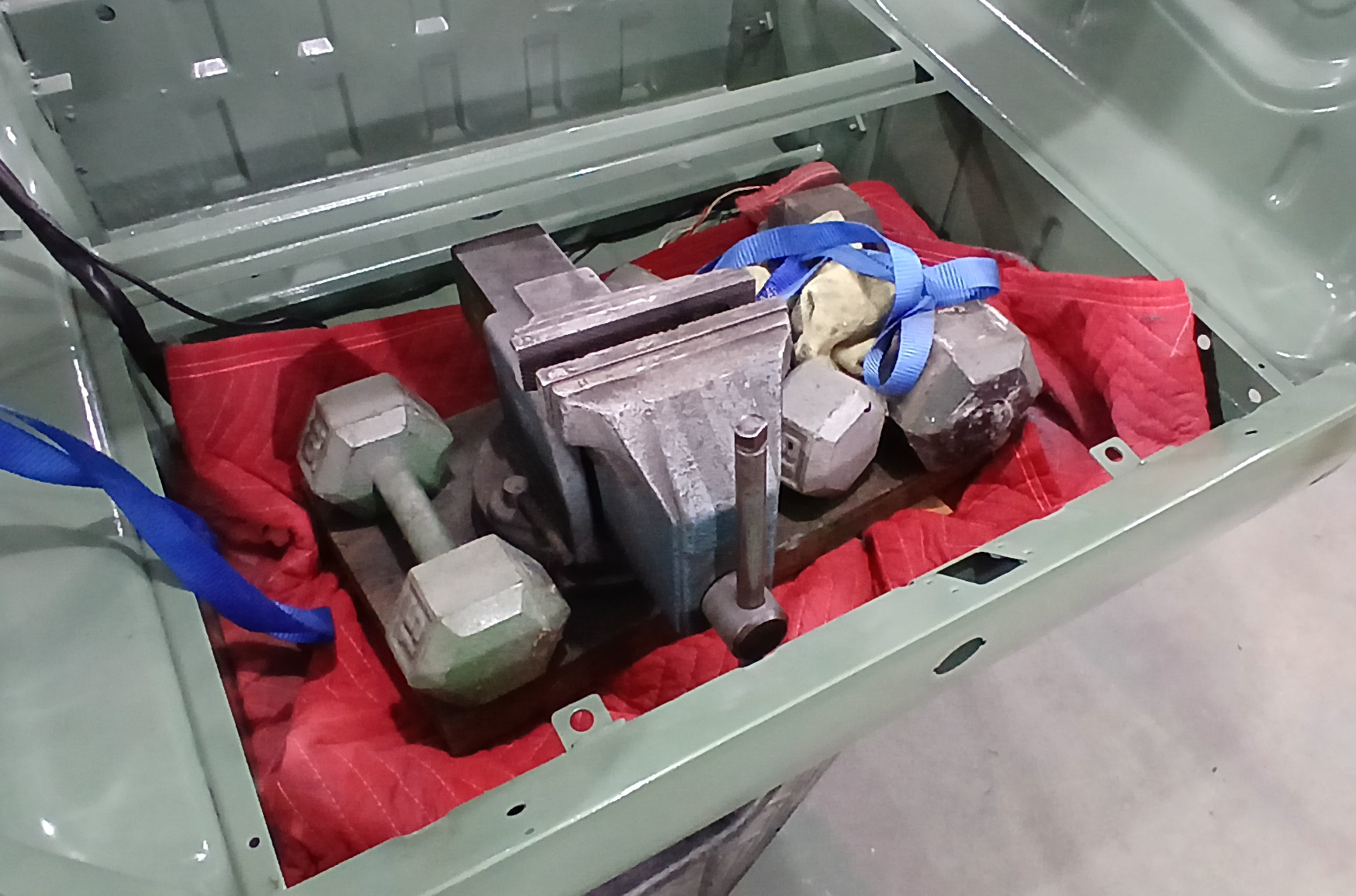
Figure 24 shows the passenger side rear axle installation completed. Figure 25 shows some additional helping hands that I needed to compress the rear springs while installing the limit straps. The empty car body is not very heavy.
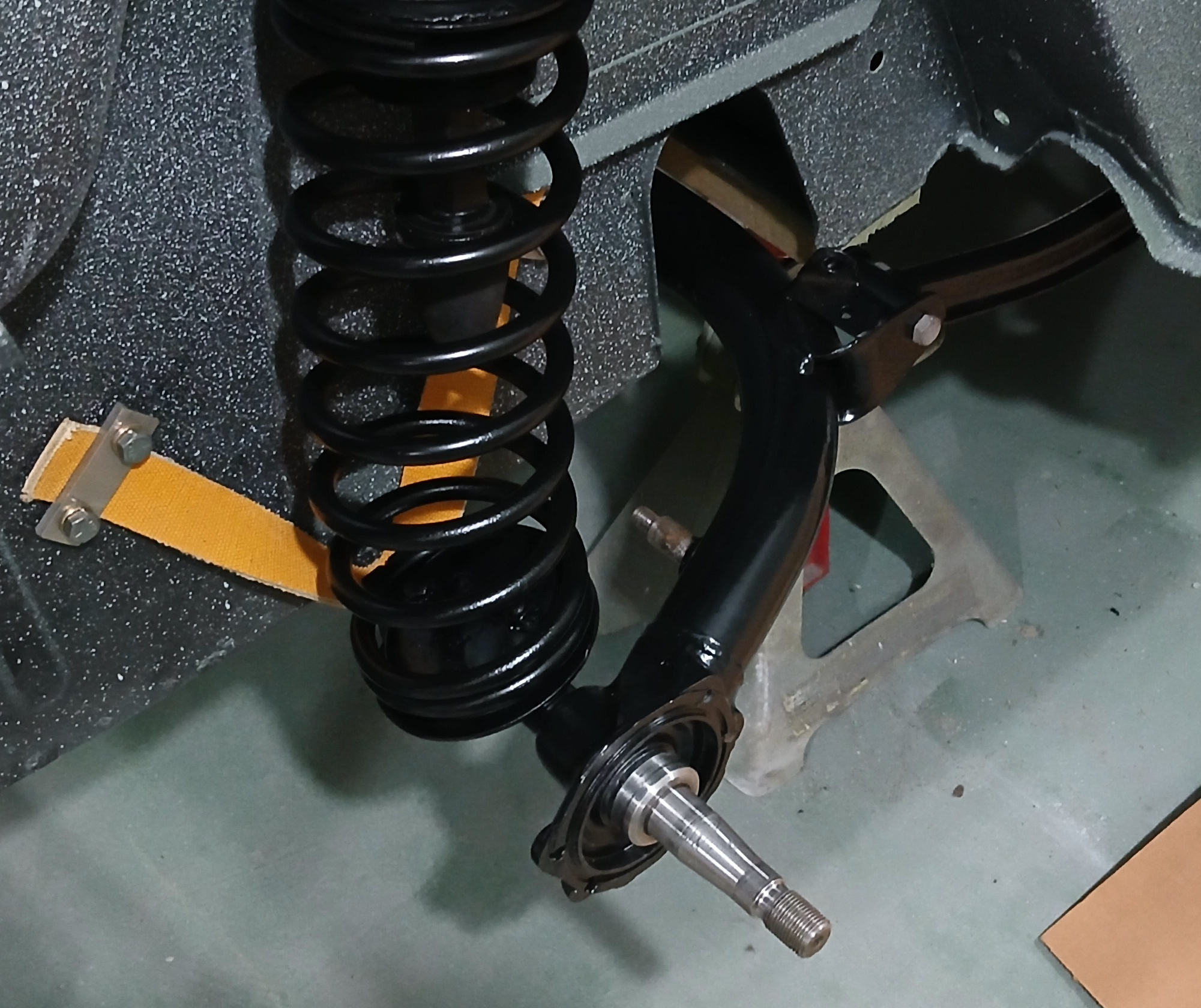
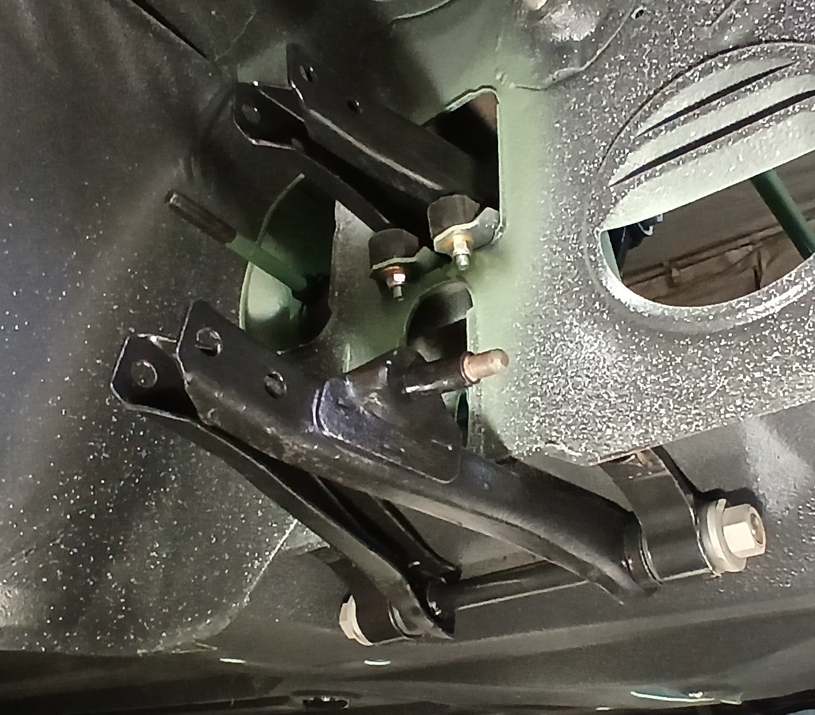
Turning my attention now to the front suspension, Figure 26 shows the result of installing the front control arms. It should be noted here that I did not tighten any bushing nuts; they were simply tightened to the point of contact but slip easily. This is true for the front and the rear. I will not torque them until the body is fully assembled and the MC850 is resting on the ground. I will the torque the bushing nuts while the control arms are in their normal resting position, Also, not knowing the number of camber/caster shims to use on the upper front control arms, I installed an equal stack at each of the four positions. I will remove shims as necessary when aligning the suspension later.
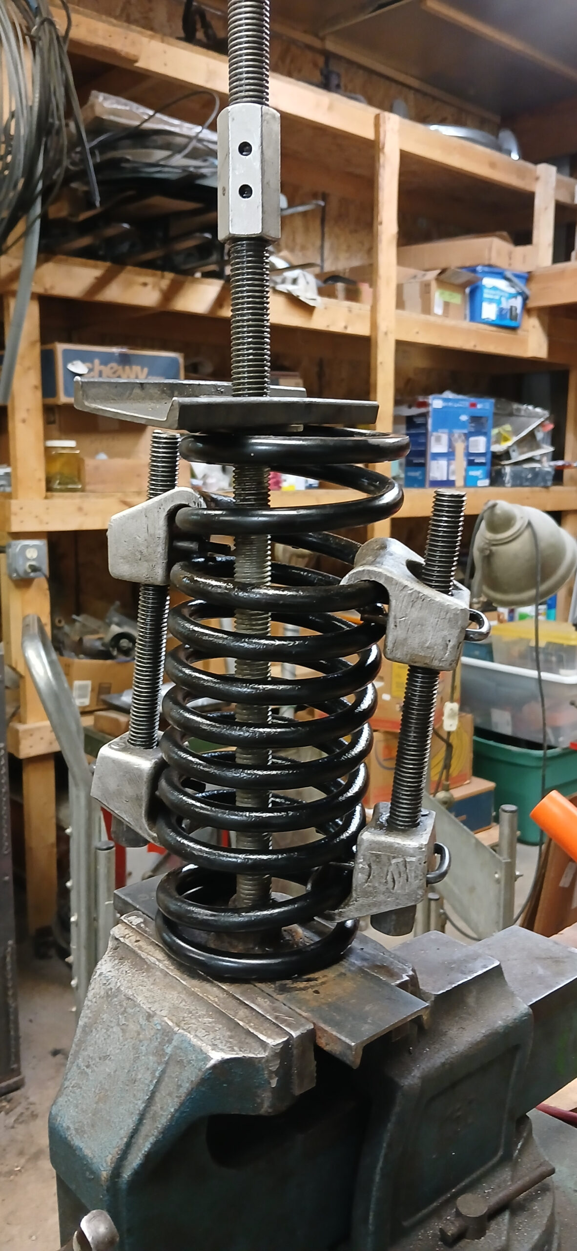
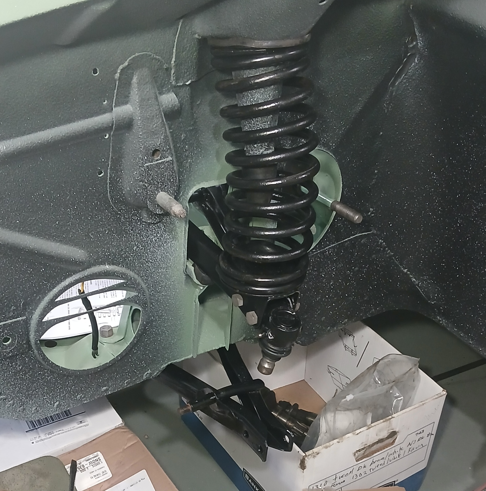
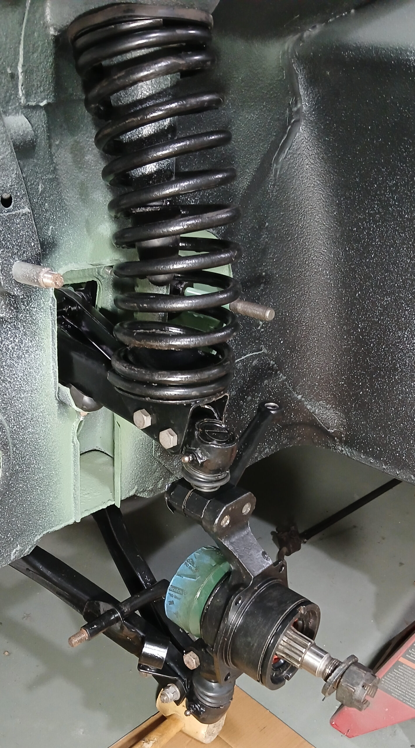
Compressing the front springs was definitely the most stressful task of this restoration. I felt like I was carrying TNT each time I took a compressed spring to the car. Figure 27 shows my home-made pre-compressor which gets the spring compressed enough to mount the cheap Monroe strut spring compressors for the final compression. I had to engage 8 coils on each side to get the spring compressed far enough. I followed the shop manual method of removing the front spring mount and placing it under the compressed spring, and then slipping the mount back onto the control arms after engaging the top of the spring with the top mount. The rubber bumper was laying loose on the mount when I did this, and I used long nose pliers to install the bumper after removing the compressor. Figure 28 shows the final, successful result.
Before installing the steering knuckle between the upper and lower control arms, I decided to press the CV joint and shaft into the knuckle. Figure 29 shows Red Line CV-2 grease being used to lubricate the CV before pressing it into the knuckle. Figure 30 shows the successful installation. I covered the CV with a makeshift cover to keep dust and dirt out.
Getting Wheels and Tires Mounted and the MC850 on the Ground
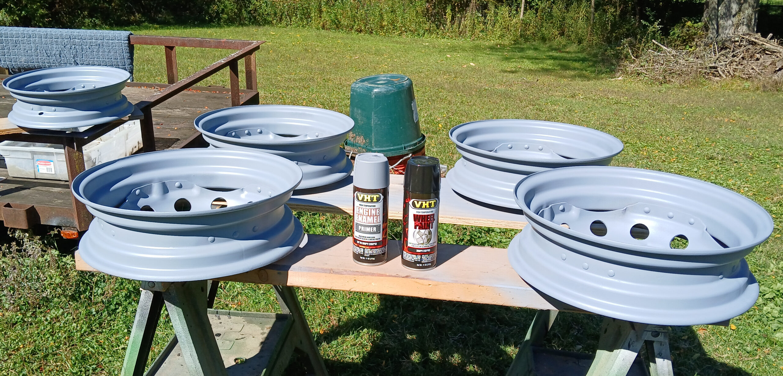
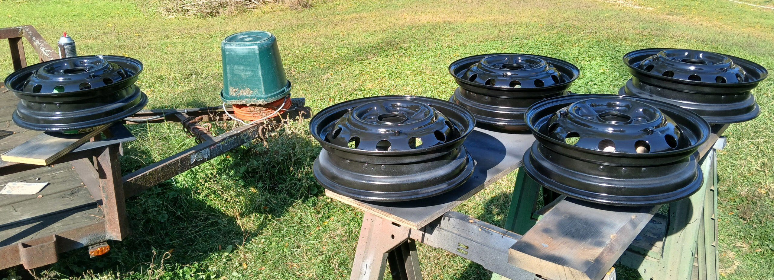
Figure 31 shows the wheels with a coat of VHT Engine Enamel Primer, and Figure 32 shows the wheels after 3 coats of VHT Wheel Paint. The backside and inside, however, got fewer coats.
In order to mount the front wheels, I first needed to mount the rotors to the hubs, and that assembly onto the shaft from the CV joint (sorry, no photos). Figure 33 shows an old wheel and a length of pipe acting as helping hands to prevent hub rotation while torquing the hub nuts.
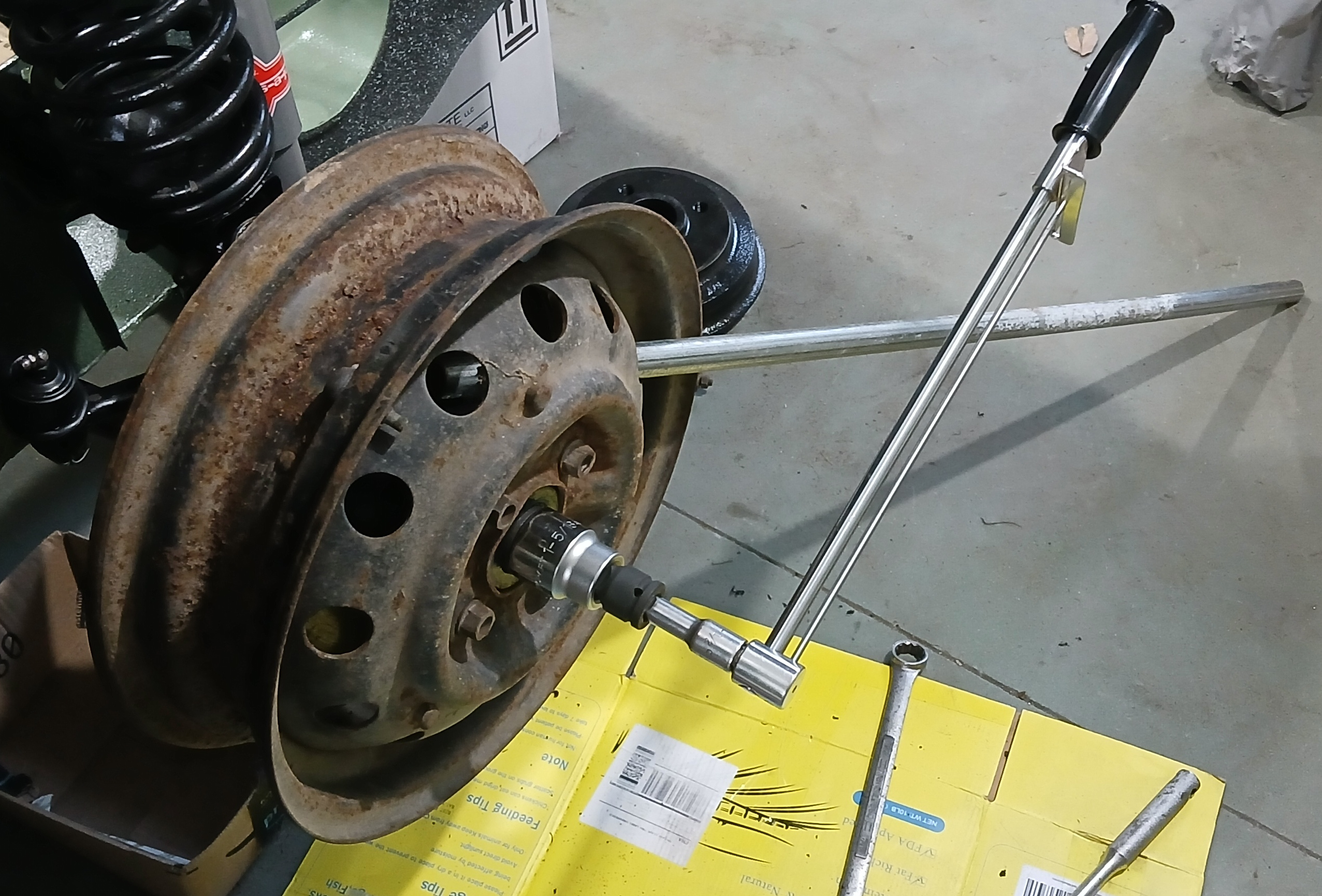
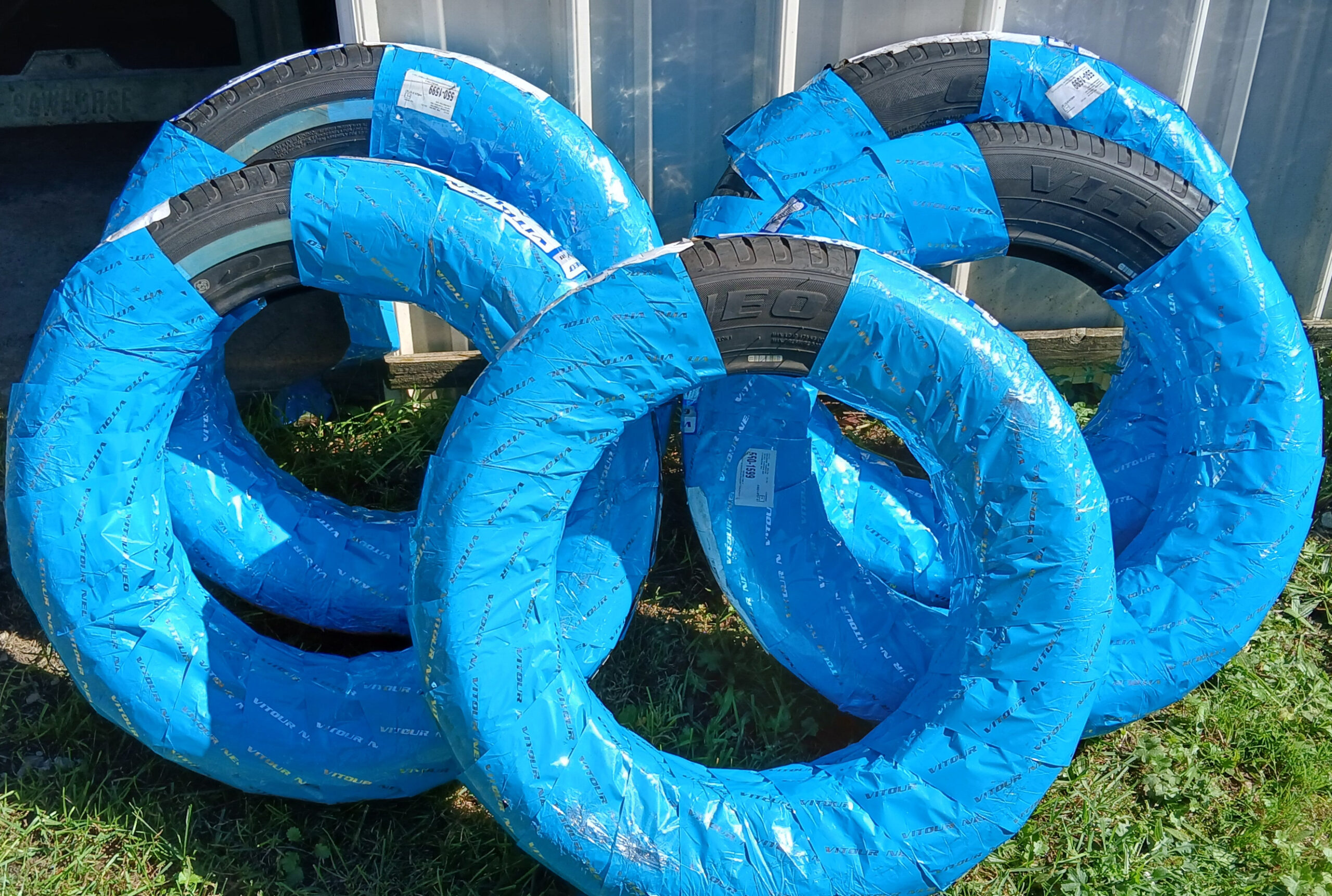
Figure 34 shows the welcome arrival of a set of 5 tires. I don’t want to sound cheap — but I am. I looked at the Vredestein, Michelin and Firestone 155/80R15 offerings which are very expensive. Despite being expensive, reviews I read from purchasers of these were not very good regarding their performance. For little more than a third of their price, I got Vitour Galaxy R1 tires with a 130 mph speed rating and AA UTQG ratings. Despite being Chinese, these got good reviews regarding traction and performance, so that’s what I got. Hopefully, they won’t be dry-rotted by the time I finish this car. Figure 34 shows their arrival, and Figure 35 shows some mounted on the rims.

The tires only come in a whitewall style, so I mounted the whitewall on the inside to hide my cheapness. I figured that was tacky looking, so I experimented with ways to blacken the whitewalls because I couldn’t find good solutions on the web. Figures 36 and 37 show what I came up with after experimentation. I found that Rust-Oleum rubberized, pro grade undercoating sticks very well and seems tough and durable. I masked the whitewall with electrical tape because it curved along the whitewall easily. I then masked with cardboard cutouts. I did it this way so I could immediately remove the masking before the coating started to dry. This ensured a smooth edge of the coating.

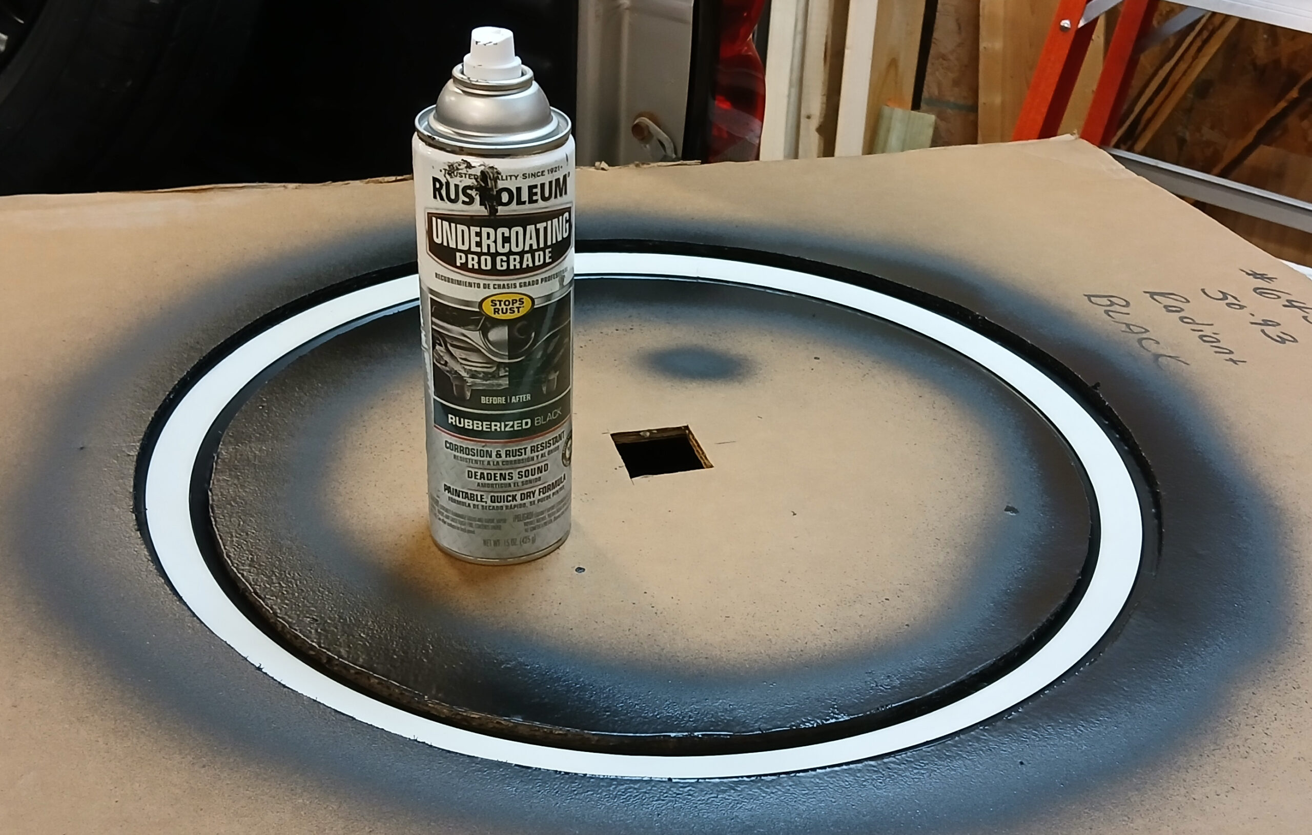
Figure 38 shows what the hidden whitewall looks like.
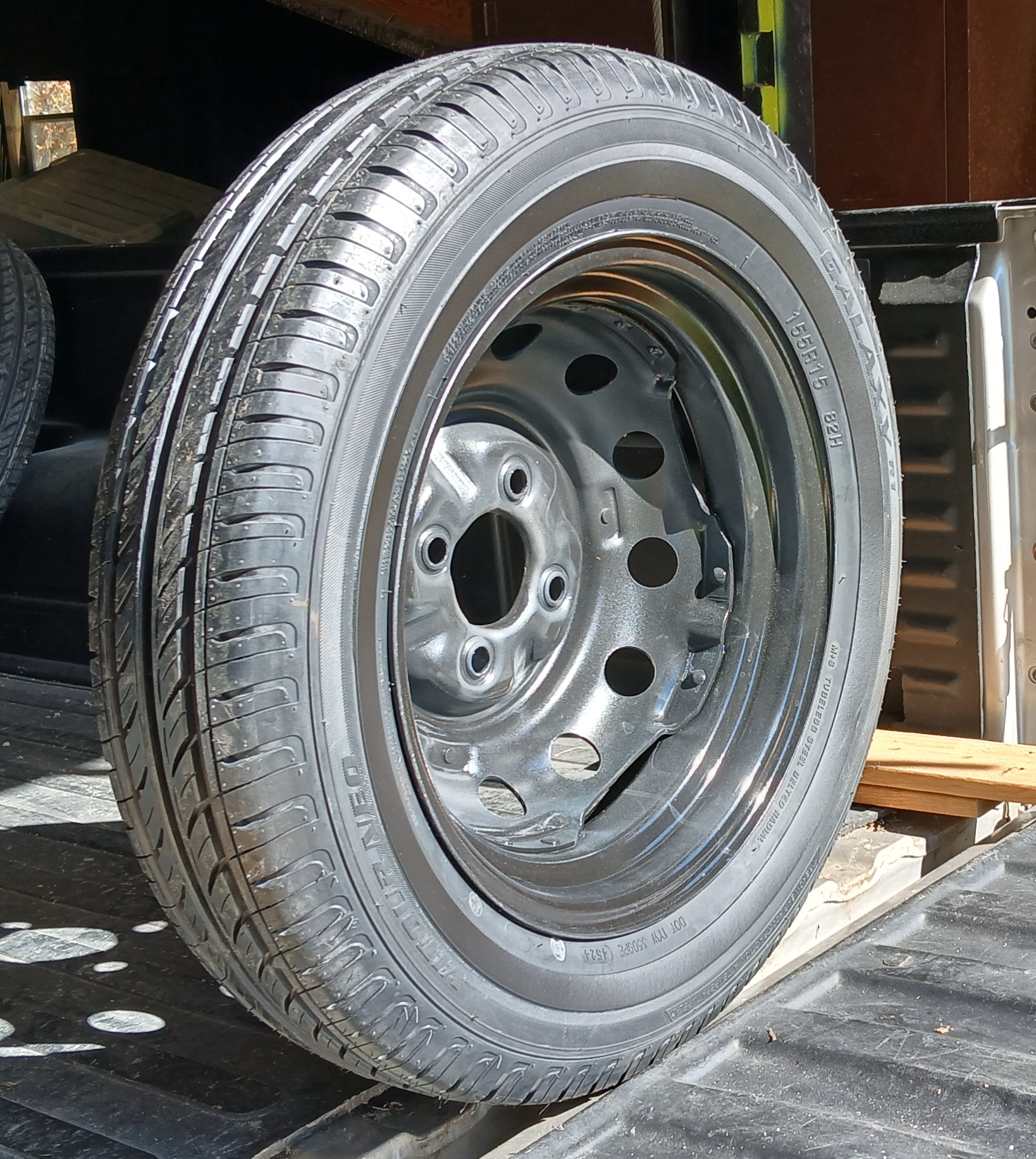
Figure 39 shows the rear brake drum bearings being greased prior to installation.
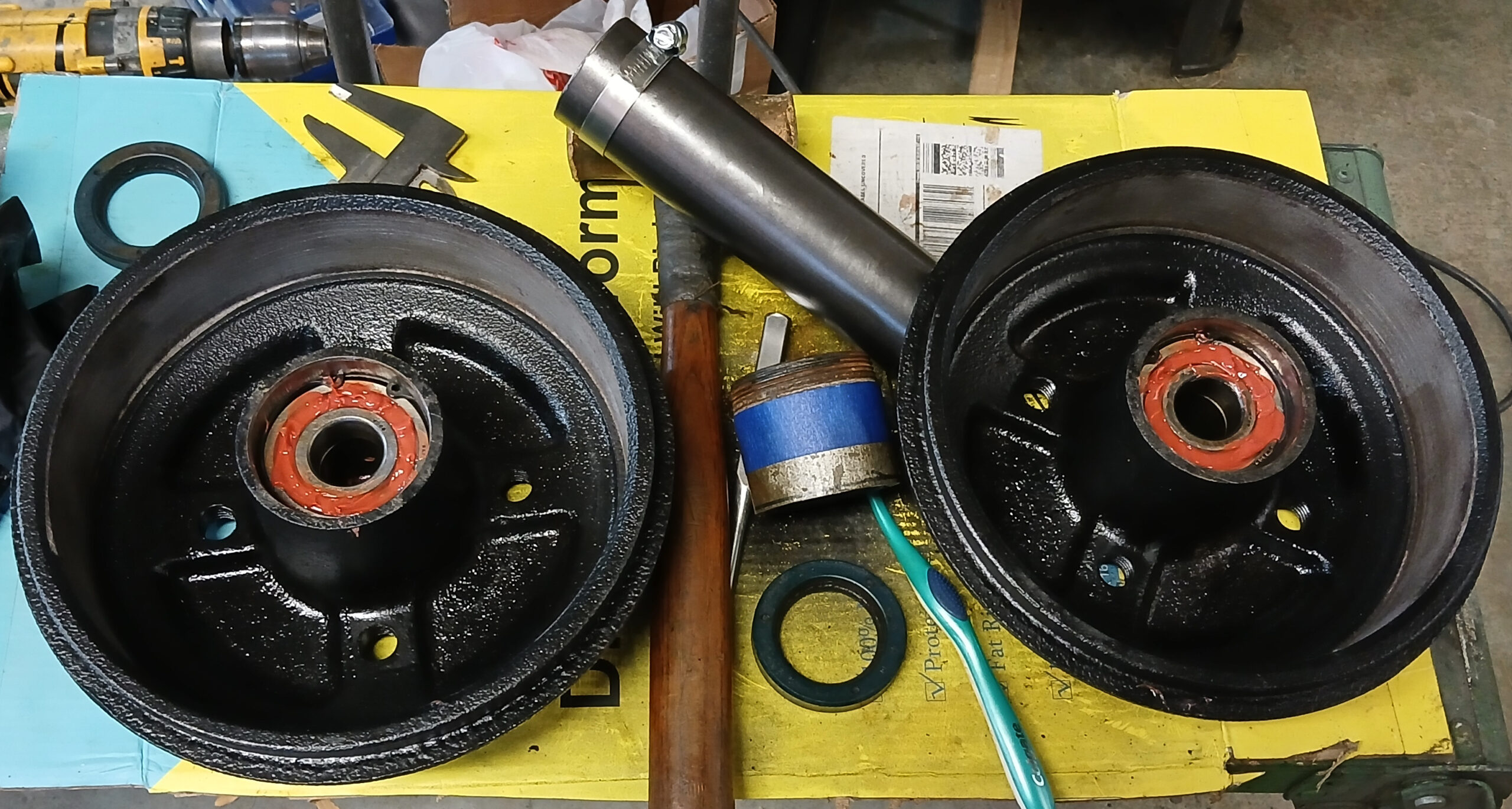
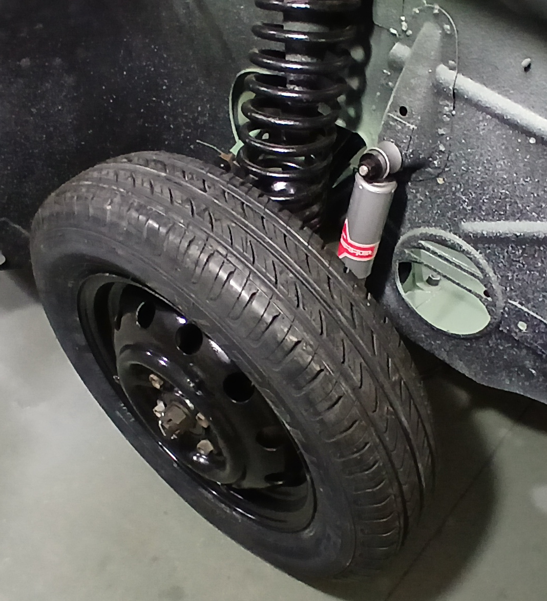
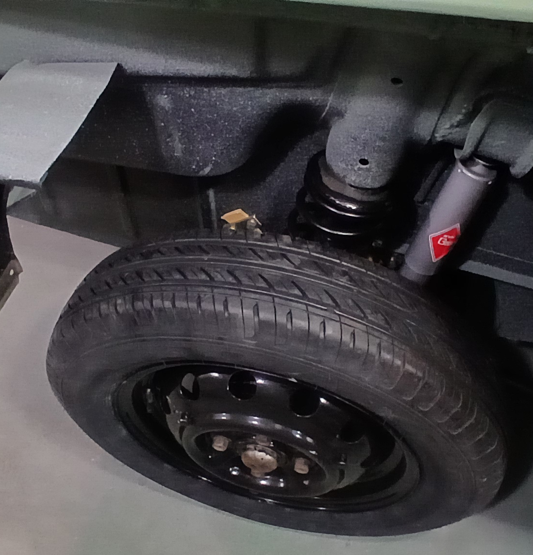
Figure 40 shows the completed front passenger side suspension, complete with Koni shock absorbers, and Figure 41 shows the same at the rear.
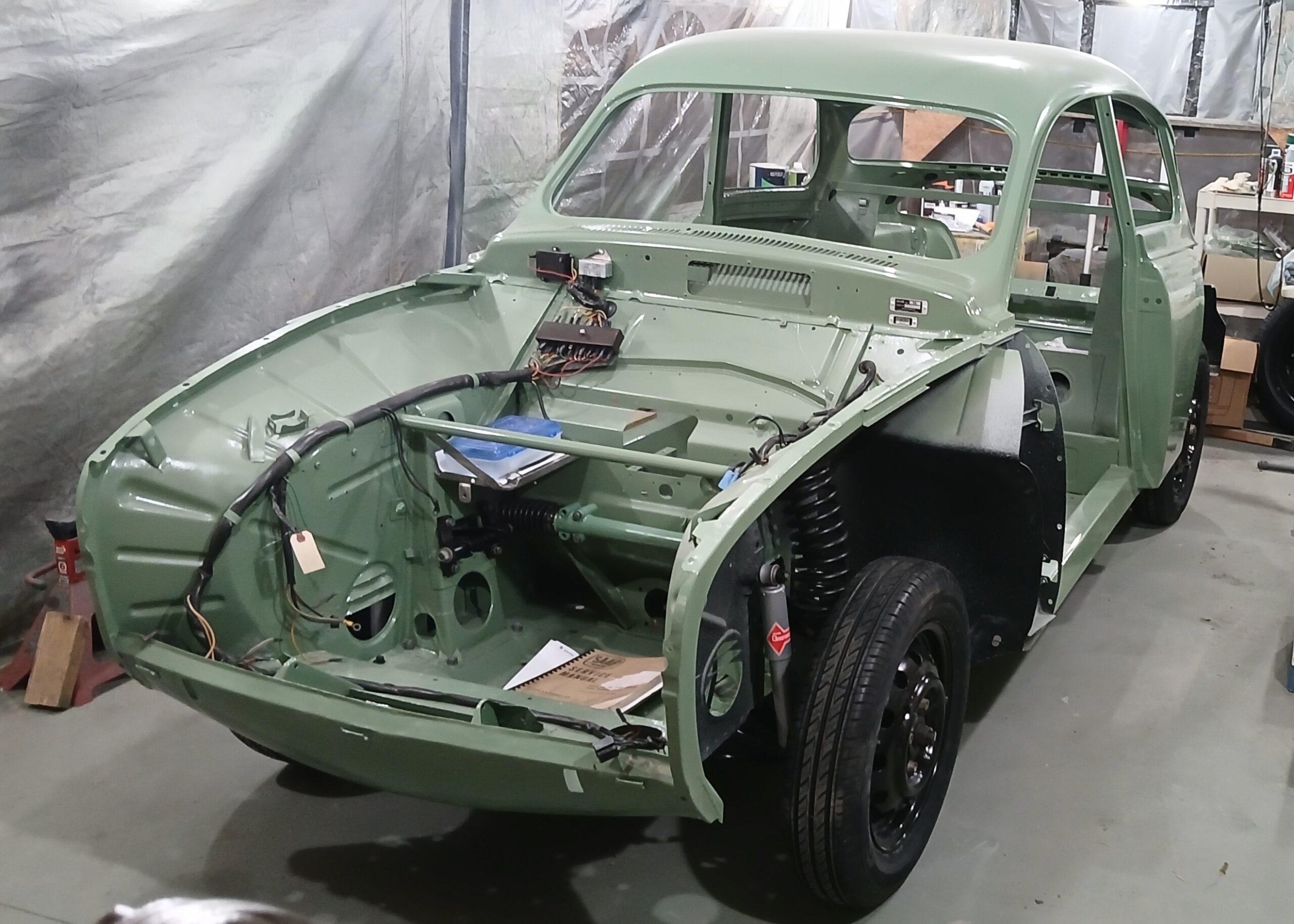
And, at long last, I have a roller as shown in Figure 42!!!
Congrats on the milestone, Ted! Appreciated the clever solutions to taking on suspension work solo.
Thanks!